WSRC-TR-2002-00448
Dissolution of Dresden Reactor Fuel
G. F. Kessinger and M. C. Thompson
Westinghouse Savannah River Company
Aiken, SC 29808
Summary
The primary goal of this work was to evaluate the effectiveness of the chop-leach process, with nitric acid dissolvent, to produce a 290 g/L [U] and 0.8 to 1.2 M [H+] feed solution for solvent extraction. The results of this study show that this processing technique is appropriate for applications in which a low free acid and moderately high U content are desired. The 7.75 L of product solution, which was over 450 g/L in U, was successfully diluted to produce ~13 L of solvent extraction feed that was 302 g/L in U with a [H+] in the range 0.8 to 1.2 M.
A secondary goal was to test the effectiveness of this treatment for the removal of actinides from Zircaloy cladding to produce a low-level waste (LLW). Analysis of the cladding shows that actinides are present in the cladding at a concentration of ~5000 ηCi/g, which is ~50 times greater than the acceptable TRU limit in LLW.
Lastly, it appears that the concentration of nitric acid (initial concentration 4 M, with 10 M added as the dissolution proceeded) was inadequate to completely digest the actinides in the UO2. The mass of insoluble material, 340 g, was much higher than expected, and analysis of the insoluble residue showed that it contained at least 200 g U.
Keywords: Uranium Oxide Dissolution, Spent Fuel Dissolution
Introduction
Head-end processing of spent nuclear reactor fuel (SNF) to prepare it for separation of fissile material from fission products and inert materials has been practiced for six decades and the experimental techniques have been discussed by numerous investigators over the past five decades.1,2,3,4 The work reported within involves the dissolution of Zircaloy 2-clad uranium dioxide (UO2) fuel. Dissolution of Zircaloy-clad UO2 fuels can be accomplished by more than one method. The Zircex process involves high-temperature chlorination of fuel cladding with HCl(g) to form ZrCl4(g), leaving the UO2 to be processed by other techniques.5,6 The Zirflex process involves dissolution of Zircaloy cladding in heated NH4F/NH4NO3, followed by dissolution of the UO2.7,8,9 These and other techniques have been extensively reviewed. An alternative to chemical removal of the cladding is mechanical decladding. For example, mechanical removal of cladding by processes such as extrusion, rolling and milling have been proposed for decladding of Al-clad fuels.
An alternative to mechanical decladding or chemical dissolution of cladding is mechanical preprocessing that exposes the UO2 to chemical attack by a dissolvent that reacts vigorously with the UO2, but slowly with the cladding. This alternative is known as the chop-leach process. In the present work, Zircaloy 2-clad UO2 fuel was treated by the chop-leach process to leach the UO2 from the cladding.
The purpose of this work is two-fold. The primary goal of this work was to use the chop-leach process, with nitric acid dissolvent, to produce a feed solution for solvent extraction that was nominally 290 g/L U and 0.8 to 1.2 M H+. A secondary goal was to test the efficacy of this treatment for the removal of actinides from Zircaloy cladding. If the nitric acid treatment can adequately leach actinides from the Zircaloy cladding, the cladding would qualify as low-level radioactive waste (LLW). If the transuranic element (TRU) content in the cladding is greater than 100 nanoCuries of TRU per gram of waste (ηCi/g), the cladding would be classified as TRU waste; lower than this value and the cladding would be classified as LLW. The LLW versus TRU waste issue is significant because of cost and difficulty associated with TRU waste disposal.
Dresden Reactor Fuel
Dresden is a boiling-water reactor located near Morris, Illinois. The sample of Dresden spent fuel used in this study was discharged from the reactor on September 1, 1975. It was subsequently obtained from Oak Ridge National Laboratory in the late 1970s in support of the Consolidated Fuel Reprocessing Program.
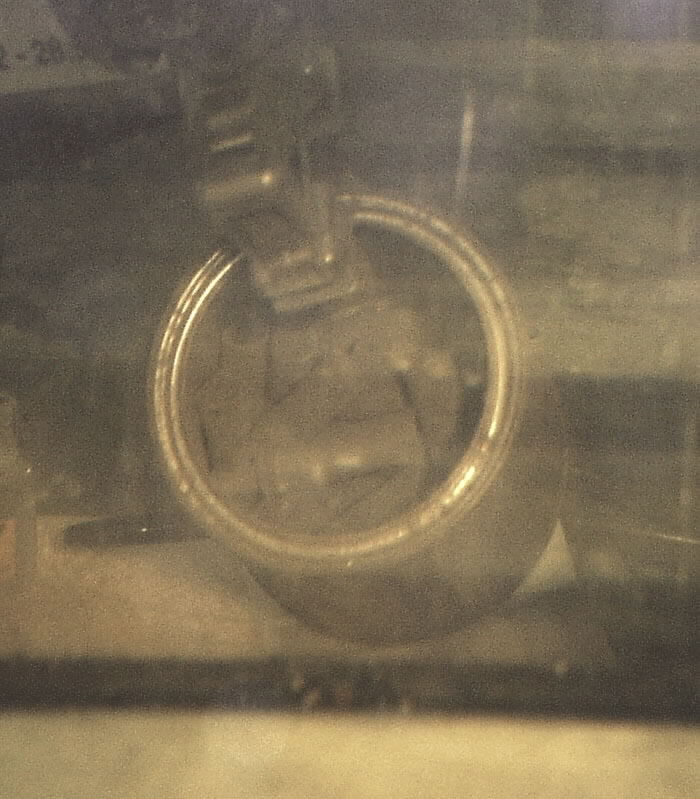
The physical appearance of the fuel is shown in Figures 1 and 2. The fuel rods were sheared to expose the UO2 before arriving at the Savannah River Technology Center.
Figure 1. Photograph (taken through remote cell window) of
as-received Dresden reactor fuel in can.
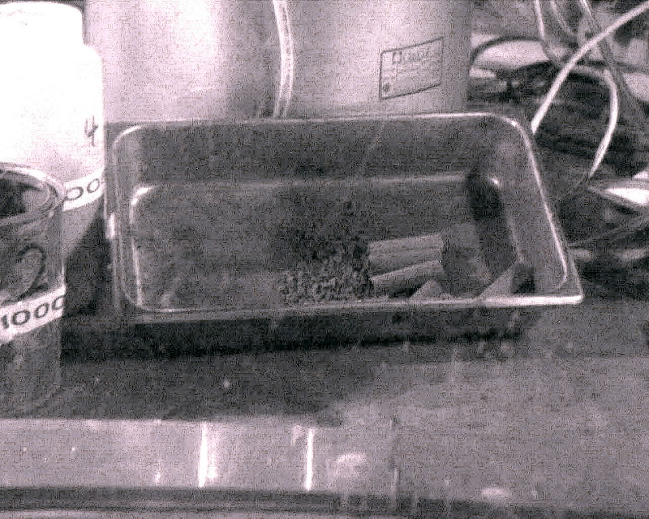
Figure
2. Photograph (taken through remote cell window) of Dresden reactor fuel as
charged
to the dissolver, showing cladding (on right) and rubble (on left).
This processing produced cylindrically shaped pieces of fuel rod ~7-8 cm (3") long, with the ends of the sections smashed to produce ellipsoidal cross-sections. This processing resulted in some sections with a portion of the UO2 intact, other sections of cladding that contained essentially no UO2, and rubble. The rubble included pieces that ranged from finely-divided, powdery-appearing material that coated the surface of the sectioned fuel rods to chunks of material with dimensions up to ~1cm. The fuel, which had been in storage at SRTC since 1979, was in three 1-liter (nominally) carbon steel cans. SRTC records show that the cans contained 3.98 kg of U and 28.54 g of Pu, and that the fuel burnup was 23,480 MWD/MT. Figure 1 shows the fuel inside one of the metal cans. Note the fuel rods have been cut into pieces small enough to be placed in the can.
Equipment
Fuel dissolution was performed remotely in a dissolver fabricated from glass. The dissolver (see Figure 3) was equipped with a glass lid that was sealed to the vessel with an o-ring and clamp, and a mesh stainless steel bucket that facilitated charging of the dissolver and removal of the leached fuel cladding after each dissolution. The dissolver lid was fabricated with five penetrations. The temperature of the solution was measured using an ungrounded, 304 stainless steel sheathed, type "K" thermocouple (purchased from OMEGA) connected to channel #1 on an OMEGA model 199 multi-channel thermocouple readout. Solutions were transferred to and from the dissolver by a peristaltic pump through dip tubes entering the dissolver through two other penetrations. One of the remaining penetrations was equipped with a condenser. The other penetration was plugged with a stopper during dissolution, but could be fitted with a funnel for addition of finely-divided solids that might otherwise pass through the mesh of the stainless steel basket. The dissolver was heated with a heating mantle powered by a 120 V variable voltage source.
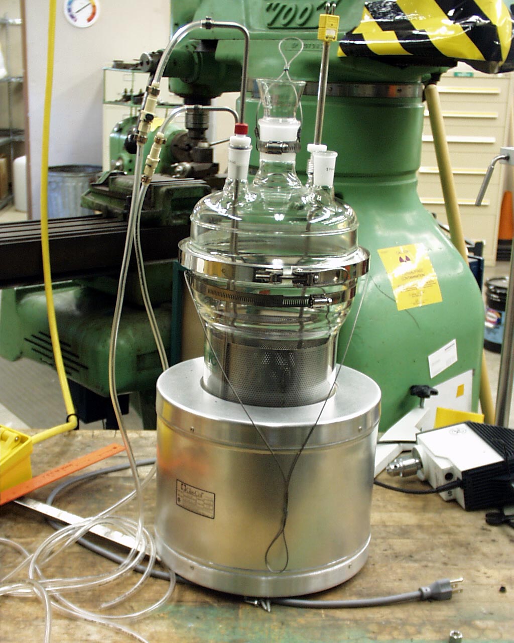
Figure
3. Dissolver with heating mantle on benchtop in mock-up
laboratory before introduction to remote cell.
Experimental Methods
The general approach to fuel dissolution, which is based on previously published work,10,11,12,13 is described below. The general approach is accompanied by a specific description of the experimental activities associated with the actual dissolution experiments.
General Considerations
Prior to the first dissolution, the fuel was batched into four fractions so it could be weighed on a triple beam balance (balance # GT1-479, 6/28/00) in the cell; the masses are shown in Table 1. The total mass of fuel available for dissolution was 4.496 kg.
Table 1. Masses of fuel batches
|
Fuel Fraction |
Mass (fuel + container)/grams |
|
M000552-1 |
1063 |
|
M000552-2 |
1486 |
|
M000552-3 |
1582 |
|
M000552-4 |
1039 |
The fuel masses (for each dissolution) were determined either by weighing the fuel container "by difference" or by weighing the fuel on a piece of smooth paper. The UO2 was dissolved using hot HNO3. Initially, the dissolver was charged with ~1L of 4 M HNO3, to which the basket containing the fuel was introduced. Reaction of the fuel with the acid was immediate, and the generation of NO2 vapor (hereafter referred to as "brown vapor") was easily observable through the cell window. The temperature increase due to addition of the solution was generally quite modest. Ambient temperatures in the cell were around 30°C and the maximum temperatures after fuel addition (but before heating) were near 40°C. Once the temperature increase ceased, the dissolver was heated and 10 M HNO3 was added to the mixture. Using the combination of the heat produced during the exothermic dissolution reaction and the heating mantle, the temperature was increased to ~ 90°C. The amount of 10 M acid added was determined by estimating the amount of acid required to completely dissolve the UO2 and produce a product ~1.5 M in H+(aq) and over 400 g/L U, based on the chemical reaction:
UO2(s) + 4HNO3(aq) = UO2(NO3)2(aq) + 2NO2(g) + 2H2O(l).14
The addition rate for acid was based on the temperature of the reaction vessel (the desire was to keep T≈90°C) and the opacity of the brown vapor in the dissolver. When leaching of the UO2 from the cladding was complete, the dissolver solution was pumped into a 20 L polyethylene carboy. In general, each batch required ~14 hours of dissolution time spread over two to three days. Before the cladding was removed from the dissolver, ~1L of 4 M HNO3 (that was to be used as the starting dissolvent for the next dissolution) was added to the dissolver, and the solution was heated to ~ 90°C for 2-6 hours. The leached cladding was then removed from the dissolver and the next batch of fuel was charged to the partially spent acid heel.
Dissolution #1
The first dissolution involved 1826 g of fuel: 1432 g from fraction M000552-3 and 494 g from fraction M000552-4. The dissolver was charged with a heel of ~1 L of 4 M HNO3, to which the basket containing the fuel was introduced.
This dissolution occurred over a period of three days (during which time the solution was twice heated to ~80°C for ~2 hours), followed by a longer (~6 hour) heating to ~90°C on the third day. After charging the fuel to the acid, and placing the lid on the dissolver, the temperature was observed to be 35°C and brown vapor was present in the dissolver. When the temperature stabilized, ~1 L of 10 M HNO3 was added to the mixture; this addition resulted in more brown vapor. After ~10 minutes the temperature was 41°C; an additional half liter of 10 M HNO3 was added during this initial heating. An additional half liter of 10 M HNO3 was also added during the second heating. During the third heating, the mixture was held at ~90°C for ~6 hours.
After the dissolver had cooled overnight, the contents of the dissolver were inspected. This inspection revealed hollow pieces of cladding (in the basket), a dark-colored liquid, and dark-colored solids. The solids appeared to be floating on the surface of the liquid, stuck to the inside wall of the dissolver and stuck to the cladding. The dark colored liquid was pumped to the product collection vessel. After the liquid was removed from the dissolver, ~700 mL of 4 M HNO3 were added to the dissolver and the basket and cladding were returned to the dissolver. The dissolver was heated to ~90°C and the cladding was allowed to soak in the fresh acid for 3-4 hours at this temperature before it was removed from the dissolver. No brown vapor was observed in the dissolver during this heating.
The cladding was rinsed, separated from free liquid, and placed in a container. A representative photograph of leached cladding is shown in Figure 4. The left hand photograph shows leached, rinsed cladding. The right hand photograph shows the view through a hollow leached, rinsed section of cladding. The mass of recovered cladding was 425 g. Using this mass, it was concluded that 1400 g of UO2 were dissolved. If it was assumed that the 1400 g were entirely UO2, this mass and the volumes of acid added may be used to compute approximate values for [U] and [H+], 411 g/L and 3.26 M, respectively.
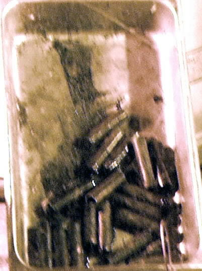
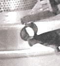
Figure 4. Photographs of cladding taken through cell window.
Dissolution #2
The second dissolution involved 1350 g of fuel: 908 g from fraction M000552-1 and 442 g from M000552-4. The fuel basket was charged to the dissolver heel (the 700 mL of acid added to leach the cladding from Dissolution #1) while the heel was still warm (~60°C). The temperature of the dissolver increased to as high as 78°C over a period of 7 minutes due to the heat produced by the dissolution reaction. After 13 minutes the temperature was fairly steady at 77°C. The mixture was allowed to slowly come to room temperature overnight.
During the second heating ~500 mL of 10 M HNO3 were added to the dissolver. After ~2 hours, the dissolver product from Dissolution #1 was pumped into the dissolver. The addition of the dissolver product resulted in the generation of brown vapor in the dissolver. The reason for reintroduction of the dissolver product to the dissolver was two-fold. First, it was believed that additional acid was required to complete the dissolution. Second, the dissolver product was >3 M in acid, which was ~2 times greater than desired. After the solution had been heated to ~90°C for another 4 hours, the dissolver was opened and the contents of the basket inspected. Inspection of the cladding showed that UO2 was still present in some sections of cladding, so the dissolver was heated again (to ~90°C) for an additional 9 hours. At the end of this heating, no UO2 was visually detected in the cladding, and the dissolver product was pumped to the product vessel.
Approximately 1.3 L of 4 M HNO3 was pumped into the dissolver, the basket containing the cladding was placed in the dissolver, and the dissolver was heated ~2 hours at temperatures near 90°C. The mass of cladding recovered from this dissolution was 73 grams.
Calculations were performed to estimate the acidity and U content of the product solution. Based on the masses of fuel dissolved and the amount of acid added, it was estimated that the product solution was ~450 g/L U with no excess H+(aq), and that the residue that contained 300-400 g of U. It is likely that any undissolved UO2 was partitioned between the dissolver vessel and the product vessel.
Dissolution #3
The remainder of the fuel, contained in fraction M000552-2 (1320 g), was charged to the dissolver. The temperature increased from 28°C to 41°C upon fuel addition. The dissolver was heated and ~450 mL of 10 M HNO3 were added. After heating to ~90°C for a period of ~5 hours and adding ~400 mL of 0.5 M HNO3 to rinse the fuel storage containers and as well as another ~400 mL of 4 M HNO3, the contents of the dissolver were inspected. The sections of fuel inspected appeared to be intact, so additional 10 M acid (~250 mL) was added to the dissolver and the dissolver was heated for another 2 hours (until brown vapor was no longer visible in the dissolver). Inspection of random fuel pieces revealed partially digested material, so more 10 M acid was added (~850 mL) over a period of 9 hours while the dissolver was heated again to ~90°C. At the end of this heating regimen, there was still brown vapor visible in the dissolver vessel but it appeared to be dissipating. Inspection of the cladding showed pieces devoid of UO2.
At the end of the first two dissolutions, the dissolver product was pumped out of the dissolver and fresh acid was added to leach the cladding. Since a final [H+] of ~1.5 M was desired, and the [H+] of the dissolver product solutions were unknown, no additional acid was added to the dissolver product. Instead, the cladding was allowed to soak for 7 hours in the dissolver product, at ~90°C, in an attempt to leach actinides from the cladding.
After cooling overnight, the dissolver was opened and the contents inspected. Along with the cladding, the basket was nearly filled with what appeared to be precipitated solids. The material appeared crystalline, with both needle-shaped and plate-like shapes that had shiny, faceted surfaces. It was theorized that this material was UO2(NO3)2·xH2O that had precipitated from the solution due to evaporation of water.
Initially, the dissolver product from the first two dissolutions was recirculated through the dissolver vessel in an attempt to dissolve the precipitated material. While this treatment resulted in partial dissolution of the precipitate, there was still a large volume of crystalline material present. Next, ~2.4 L of de-ionized water was added to the vessel and heated. This treatment appeared to solubilize the remaining crystalline material (large needles and platelets); however, there was still finely divided material present in the dissolver. It was supposed that this material was primarily the noble-metal fission products that were insoluble in nitric acid. Approximately 215 g of cladding were recovered from the dissolver.
Filtering Dissolver Product Solution
After the completion of the third dissolution, the products from the three dissolutions were homogenized and filtered with Nalgene MF75 Series Disposable Sterilization Filter Units with type CN general-purpose membrane (0.45 μm pore diameter). As much insoluble material as possible was removed from the interior walls of the dissolver and the filter media and dried at temperatures below 100°C. The mass of collected material was 341 grams. Samples of the residue and the dissolver product were submitted to the SRTC Analytical Development Section (ADS) for analysis.
The residue was placed in a stainless steel beaker and stirred and heated with ~150 mL of 10 M HNO3. No gas evolution was observed. Approximately 0.05 moles KF (0.301 grams) was added to the slurry. After heating and stirring, this solution was diluted to ~500mL with 0.5 M HNO3, and the solution was heated and stirred on a combination hotplate-stirrer. Analysis of the resulting solution showed that it was 424 + 44 g/L in U (uncertainties for all U analyses are reported at the 95% confidence level). This corresponded to approximately 210 g of U; however, approximately 100 mL of this solution was spilled in the cell, so ~400 mL of 424 + 44 g/L U solution was recovered and added to the ~7.4 L of 494 + 20g/L U dissolver product.
Results and Discussion
The products of the initial three dissolutions, cladding, dissolver product and insoluble residues were sampled and submitted to the SRTC ADS for analyses. Requested analyses included gamma scan (γ scan), alpha pulse height analysis (αPHA), inductively coupled plasma-emission spectroscopy (ICP-ES), and inductively coupled plasma-mass spectrometry (ICP-MS).
Mass of Dissolved Material
As stated in the Experimental section above, 4.496 kg of fuel and cladding were charged to the dissolver during the three dissolutions. The solids recovered from the dissolver subsequent to those dissolutions included 341 g of insoluble, finely-divided solids and 713 g of cladding, for a total of 1.054 kg of insoluble material. The mass of the soluble material was computed to be 3.442 kg. During the subsequent leaching of the 341 g of material, all but ~17.9 g were dissolved, resulting in a total of 3.765 kg of soluble material.
Insoluble Residues
Samples of the insoluble residues were submitted to ADS for dissolution and analysis. Replicate samples were dissolved by each of two procedures, aqua regia dissolution and KOH fusion. Aliquots of the aqua regia product and the solution produced from the KOH fusion were analyzed by ICP-MS, ICP-ES, as well as alpha and gamma counting. Due to the limited scope of the present discussion, it is not possible to show and discuss all the analytical results in this report. Instead, the ICP-MS results for the actinides will be presented in Table 2 below. These results are the mean values for five ICP-MS analyses of the insoluble residue. Based on these results, it was estimated that more than 100 g U and 5.1 g Pu remained in the insoluble material. (For this discussion it is assumed that all the mass 238 signal is U and all the mass 241 is Am.)
Table 2. Averaged ICP-MS Results for Insoluble Solids
|
Mass/z |
Element |
μg element/g sample |
|
235 |
U |
1268 |
|
236 |
U |
741 |
|
238 |
U(major), Pu(minor) |
229167 |
|
239 |
Pu |
8971 |
|
240 |
Pu |
5010 |
|
241 |
Am(major), Pu(minor) |
704 |
|
242 |
Pu |
1043 |
Since the insoluble residues contained so much U and Pu, these solids were placed in a stainless steel beaker with 140 mL of 10 M HNO3 and heated to 90-95°C for several hours while stirring. There was no visible sign of reaction during heating, and extensive solids were still present, so KF and 0.5 M HNO3 were added to form ~500 mL of solution 0.01 M in F- (0.302 g KF), and the mixture was heated and stirred. The solution was filtered to give ~500 mL of solution (of which ~100 mL was spilled). The filtered and dried solids that remained weighed 17.94 g. Analysis of the leachate by a spectrophotometric technique15 showed that it was 424 + 44 g/L in U. This solution was ultimately added to the dissolver product solution.
Cladding
One sample of cladding (~0.25 g) was submitted for a suite of analyses to determine the uptake of fission products and actinides by the cladding. The results of those analyses are shown in Table 3.
The cladding sample was digested in HF(aq); there was no indication that any of the sample failed to dissolve. Separate aliquots of the solution were used for the three analyses. Based on the mass of cladding recovered, ~710 g, and these analyses, the effectiveness of the dissolution process for leaching Pu and U from the cladding can be evaluated. Presence of TRUs in the cladding at levels greater than 100 ηCi/g of cladding would result in the cladding being a TRU waste instead of a LLW. One purpose of the post dissolution leaching of the cladding was to attempt to reduce the TRU level in the cladding to below the 100 ηCi/g TRU waste threshold. The upper limit of Pu uptake by the entire 711 g of cladding was 3.10 mg (the actual level is somewhat lower, but it is not possible to differentiate the α PHA signals resulting from Pu-238 and Am-241 so it is assumed that all the signal was a result of Pu-238). The total U dissolved in the cladding was 442 mg. The ratio, U:Pu in the cladding, 143:1, is in good agreement with the initial U:Pu in the spent fuel before dissolution, 139:1. This indicates that the efficiency of U leaching from the cladding was roughly equivalent to that for Pu. Lastly, these results show that the cladding produced from these dissolutions would be expected to be a TRU waste, as the TRU isotope content is about 5000 ηCi/g, unless leached further to reduce the TRU content.
Table 3. Analytical results for cladding (not including Zr)
|
Element |
μg/g sample |
|
Ag |
5340 |
|
Al |
786 |
|
B |
5050 |
|
Ba |
35.4 |
|
Ca |
<20.2 |
|
Cd |
<3.70 |
|
Cm-244 |
0.00305 |
|
Ce |
4380 |
|
Co -60 |
0.00248 |
|
Cr |
815 |
|
Cs-137 |
1.87 |
|
Cu |
72.5 |
|
Eu-154 |
0.00426 |
|
Fe |
1500 |
|
Gd |
174 |
|
K |
<826 |
|
La |
76.3 |
|
Li |
<37.9 |
|
Mg |
57.8 |
|
Mn |
21.0 |
|
Mo |
461 |
|
Na |
3410 |
|
Ni |
<11.9 |
|
P |
<60.7 |
|
Pb |
<28.1 |
|
Pu-239/240 |
4.08 |
|
Pu-238/Am-241 |
0.292 |
|
Sb |
<333 |
|
Sb-125 |
0.00130 |
|
Si |
44000 |
|
Sn |
13000 |
|
Sr |
423 |
|
Ti |
28.4 |
|
U |
623 |
|
Zn |
25.6 |
Dissolver Product
The dissolver product was submitted to ADS in a diluted form for chemical analyses. Due to the high fission product content, the solution was diluted by a factor of nearly 10,000 before submission for analyses. This high dilution resulted in a solution for which many minor components were below detection limits, so the results presented below are not complete. After the dissolver product was mixed with the leachate and diluted to form the solvent extraction feed, a less dilute sample was submitted for analyses. Those analyses are partially complete and are also discussed below.
Density Determination
Because sample dilutions and sample titrations are performed by mass in the remote environment, it is necessary to know the density of all solutions involved in these activities. The mass of a known volume of the dissolver product solution was determined remotely by weighing a 100 mL volumetric flask, filling the flask with filtered dissolver product, weighing the filled flask, and computing the difference (full flask empty flask). This value, along with the volume of the volumetric flask, was used compute the density of the solution. Table 4 shows the data from a single density measurement; the density of the solution was taken to be 1.7356 g/mL.
Table 4. Density data for dissolver product
|
Mass of filled 100.00 mL flask |
196.948 g |
|
Mass of empty 100.00 mL flask |
23.391 g |
|
Mass of solution |
173.558 g |
|
Volume of solution |
100.00 mL |
|
ρ |
1.7356 g/mL |
Free Acid Determination
The free acid concentration of the dissolver product was determined by titrating, by mass, aliquots of the dissolver solution with standardized NaOH solution (Fisher lot no. 024521-24, 0.1000 + 0.0005 N NaOH), the density of which was measured remotely (ρ = 1.00808 g/mL: see Table 5 for data). The titration was a double end point titration. The first endpoint, which occurred at a pH in the range 5.0 to 5.5, was for the weak acids in the solution (which includes soluble metals, especially U). This endpoint was identified visually by the turbidity of the solution resulting from the formation of UO2(OH)2. The second endpoint, which was a result of H+ neutralization, occurred at pH ~6.5. A portable pH meter (Corning model pH-20) was used to measure pH. The pH meter was either calibrated at a single pH (7) or at two values (4 and 7) before use. A magnetic stirrer was used to stir the solutions. The measurement was replicated 5 times and the results averaged to obtain a free acid concentration of 1.45 M.
Table 5. Density data for standardized NaOH
|
Mass of filled 100.00 mL flask |
124.257 g |
|
Mass of empty 100.00 mL flask |
23.449 g |
|
Mass of solution |
100.808 g |
|
Volume of solution |
100.00 mL |
|
ρ |
1.0081 g/mL |
Uranium Determination
A sample of solution diluted to ~7g/mL U in ~1 M HNO3 was submitted to ADS for analysis. The remote spectrophotometric determination of U in the dissolver product gave a result of 494 + 20 g/L U (corrected for dilutions).
Solution Combination and Dilution
After the analyses of the dissolver product and leachate from the HNO3/KF treatment of the insoluble solids, they were combined to form a single product solution with a volume of ~7.75 L. This solution was then diluted with 5 L of 0.1 M HNO3 and 0.25 L of 3 M HNO3 to form ~13 L of solution. A diluted aliquot of this solution was submitted for a suite of analyses to determine the elemental composition of solutes; these results are shown in Table 6. Another aliquot diluted to ~7g/mL U in ~1 M HNO3 was submitted to ADS for spectrophotometric determination of U; the result of this analysis is also shown in Table 6. In addition, the density of the product solution was measured twice; the average of the two determinations was 1.436 g/mL.
Table 6. Chemical analysis of diluted product solution
|
Component |
Analytical Results |
|
Free Acid, M |
0.84 |
|
U, g/L |
302 |
|
Pu, g/L |
2.16 |
|
Np, g/L |
6.8 E-05 |
|
Am, g/L |
0.23 |
|
Cm, g/L |
0.005 |
|
99Tc, g/L |
1.68 E-04 |
|
137Cs, d/m/mL |
2.53 E+10 |
|
90Sr, d/m/mL |
2.11 E+10 |
|
154Eu, d/m/mL |
2.32 E+08 |
|
Ag, g/L |
0.78 |
|
Ba, g/L |
0.50 |
|
Ce, g/L |
1.47 |
|
Cu, g/L |
0.37 |
|
Fe, g/L |
0.07 |
|
Gd, g/L |
0.64 |
|
La, g/L |
0.49 |
|
Mn, g/L |
0.02 |
|
Na, g/L |
0.33 |
|
Ni, g/L |
0.60 |
|
Sn, g/L |
0.41 |
|
Ti, g/L |
0.11 |
|
Zn, g/L |
0.05 |
Three aliquots of the product were titrated with standard NaOH (in the same manner as was described above). The result of at least one of these titrations was considerable lower (giving a [H+] less than half that from the other two determinations. During this titration a smaller mass of product solution (0.550 g) was titrated, which increases the uncertainty of the determination as compared to the other two titrations, during which 2.455 g and 0.883 g were titrated. The average of the two higher mass determinations gave a mean [H+] value of 0.84 M (the value reported in Table 6).
Conclusions
The primary goal of this work was to evaluate the effectiveness of the chop-leach process, with nitric acid dissolvent, to produce a 290 g/L U and 0.8 to 1.2 M H+ feed solution for solvent extraction. The results of this study show that this processing technique is appropriate for applications that require low free acid and moderately high U content. The 7.75 L of product solution, which was over 450 g/L in U, was successfully diluted to produce ~13 L of solvent extraction feed that was 302 g/L in U with a [H+] in the range 0.8 to 1.2 M.
While the primary goal of the study was realized, some issues were identified that require more attention. A secondary goal was to test the efficacy of this treatment for the removal of actinides from Zircaloy cladding. This goal does not appear to have been met. It is possible that the cladding was not uniformly leached (some pieces were treated for longer periods of time in more concentrated solutions), never the less, the cladding that was analyzed was about 50 times too high in actinide content to qualify as a LLW. It is possible that the failure to adequately leach actinides from the Zircaloy 2 cladding is due to the use of fairly dilute (less than or equal to 4 M) HNO3 as the dissolution media. It could be, however, that Pu and U are incorporated into the cladding as intermetallic phases, such as Zr-U, Zr-Pu, and/or Zr-U-Pu phases, that are insoluble in HNO3.16
Lastly, it is possible that the failure of nitric acid to adequately leach actinides from the spent fuel cladding is related to another apparent deficiency of this process, the inability of the nitric acid to completely digest the actinides in the UO2. The three dissolutions produced a solution that was high in U content, 494 + 20g/L, and low in acid, ~1.45 M. However, the mass of insoluble material, 341 g, was much higher than expected; analysis of the insoluble residue showed that it was high in U and Pu, and subsequent leaching of the residues produced a leachate that contained ~200 g U.
Future Studies
The most glaring uncertainties associated with the present work are related to the ability of the nitric acid dissolvent to completely digest U and Pu in the UO2 and Zircaloy cladding. While it was possible to digest the UO2 residue using an HF/HNO3 media, the addition of F- would result in greater waste volumes in a full-scale process, so it would be preferable to digest the fuel without addition of F-.
A starting point for future work would be a more thorough characterization of the cladding and insoluble solids from the present work. X-ray powder diffraction and scanning electron microscopy analyses of the residues would assist in the identification of the phases present in these materials. In addition, this information would be a starting point for possible modification of the technique. It is possible that modification of the process, by starting the dissolution with 10 M HNO3 instead of 4 M acid, would increase the acid concentration during the dissolution process adequately to digest more of the difficult residues. In addition, leaching the empty cladding with the more concentrated acid might improve the efficiency of actinide removal from the cladding. Lastly, investigation of these two uncertainties would allow a more thorough analysis of the waste management issues associated with this fuel processing technique.
References