WSRC-TR-2001-00555
Evaluating Centrifuges for Solid-Liquid Separation
in the SRS Salt Processing Program
M. R. Poirier, M. A. Noratok, and S.D. Fink
Westinghouse Savannah River Site
Aiken, SC 29808
This report was prepared as an account of work sponsored by an agency of the United States Government. Neither the United States Government nor any agency thereof, nor any of their employees, makes any warranty, express or implied, or assumes any legal liability or responsibility for the accuracy, completeness, or usefulness of any information, apparatus, product or process disclosed, or represents that its use would not infringe privately owned rights. Reference herein to any specific commercial product, process or service by trade name, trademark, manufacturer, or otherwise does not necessarily constitute or imply its endorsement, recommendation, or favoring by the United States Government or any agency thereof. The views and opinions of authors expressed herein do not necessarily state or reflect those of the United States Government or any agency thereof.
This report has been reproduced directly from the best available copy.
Available for sale to the public, in paper, from: U.S. Department of Commerce, National Technical Information Service, 5285 Port Royal Road, Springfield, VA 22161, phone: (800) 553-6847, fax: (703) 605-6900, email: orders@ntis.fedworld.gov online ordering: http://www.ntis.gov/support/index.html
Available electronically at http://www.osti.gov/bridge
Available for a processing fee to U.S. Department of Energy and its contractors, in paper, from: U.S. Department of Energy, Office of Scientific and Technical Information, P.O. Box 62, Oak Ridge, TN 37831-0062, phone: (865 ) 576-8401, fax: (865) 576-5728, email: reports@adonis.osti.gov
Summary
As a pretreatment step for the caustic side solvent extraction (CSSX) flowsheet, the incoming salt solution that contains entrained sludge is contacted with monosodium titanate (MST) to adsorb strontium and actinides. The resulting slurry is filtered to remove the sludge and MST. Testing performed by the Savannah River Technology Center (SRTC) and the University of South Carolina showed cross-flow filtration rates lower than desired for simulated salt solution containing various concentrations of MST and sludge solids (i.e., 0.02 – 0.08 gpm/ft2). Because of the low filtration rates measured during simulant and real waste testing, the authors investigated centrifugation as potential replacement for the cross-flow filters.
These tests used a pilot-scale decanter centrifuge. The centrifuge generated approximately 4100 Gs during the tests. The feed solutions for the test consisted of 5.6M sodium, average salt solution with insoluble solids. The insoluble solids in the tests included the following: (1) simulated Tank 8F sludge, (2) simulated Tank 8F sludge and MST, (3) simulated Tank 8F sludge, strontium nitrate, and sodium permanganate, and (4) simulated Tank 8F sludge, MST, and Cytec HX-400 flocculant. The insoluble solids concentration for the tests measured 0.06 wt %, 0.29 wt %, 1.29 wt %, and 6.0 wt % (measured values < 0.5 wt % to 6.5 wt %).
The conclusions from this work follow.
The testing does suggest that a centrifuge could be employed for solid-liquid separation under the following options.
Keywords: filtration, centrifuge, solid-liquid separation, sludge
Introduction
The Department of Energy selected Caustic Side Solvent Extraction (CSSX) as the preferred cesium removal technology for Savannah River Site waste.
As a pretreatment step for the CSSX flowsheet, the process contacts the incoming salt solution that contains entrained sludge with monosodium titanate (MST) to adsorb strontium and actinides. The resulting slurry is filtered to remove the sludge and MST with the filtrate processed through the solvent extraction system. Testing performed by SRTC and the University of South Carolina with simulated and real waste showed filtration rates of 0.02 – 0.08 gpm/ft2.1,2,3,4,5 Because of the low filtration rates measured during simulant and real waste testing, SRTC identified alternative solids-liquid separation technologies as potential replacement for the crossflow filters.6 One technology identified as a possible replacement is the centrifuge.7
The centrifuge relies on centrifugal force to exaggerate the density difference between the particles in a liquid, so the solids will "settle" more quickly. Thus, the centrifuge can, theoretically, completely remove even small, colloidal solids, given a long enough period of operation. Separation occurs without a physical barrier, and therefore, no place exists for trapping of the solids. Centrifuges work best with fast settling solids.
The particle settling velocity can be estimated from the following equation
where Vs is the settling velocity, Dr is the density difference between the particle and the fluid, m is viscosity, g is the gravitational constant, d is particle diameter, Wb is the rotational speed of the centrifuge bowl, and Rb is the bowl radius.8 The required settling rate is described by
![]()
where Vs,req is the required settling rate, h is the distance between internal surfaces of the centrifuge, L is the centrifuge length, Q is flow rate, and A is cross-sectional area of the centrifuge. Combining these equations gives the following expression for centrifuge flow rate
where Vs(1g) is settling rate under gravity settling, and Rav is the average radius of the bowl and the pool.8
As the equation shows, centrifuges work best with fast settling solid particles. We expect slow settling sludge particles in the feed to the Salt Processing Facility since the waste comes primarily from evaporator operations that allowed settling and removal of the larger sludge particles. Hobbs measured settling rates of solid particles in a such a sample from Tank 41H as 1 – 25 in/day.9
Centrifuges successfully treat streams in the SRS Separations canyons. They have operated since 1953. The bowls rotate at 1740 rpm and produce 1730 Gs.10,11 The canyon centrifuges have a residence time of 3 – 6 minutes10 versus 7 minutes in this test. The centrifuges separate MnO2, which precipitates to remove fission products, and silicates, which are flocculated with a gelatin strike. The feed for the centrifuges is acid rather than basic, which could affect the particle morphology. The centrifuges used there are standard milk centrifuges with the motors remoted from the bowls for ease of periodic maintenance. The bowls have not required replacement.
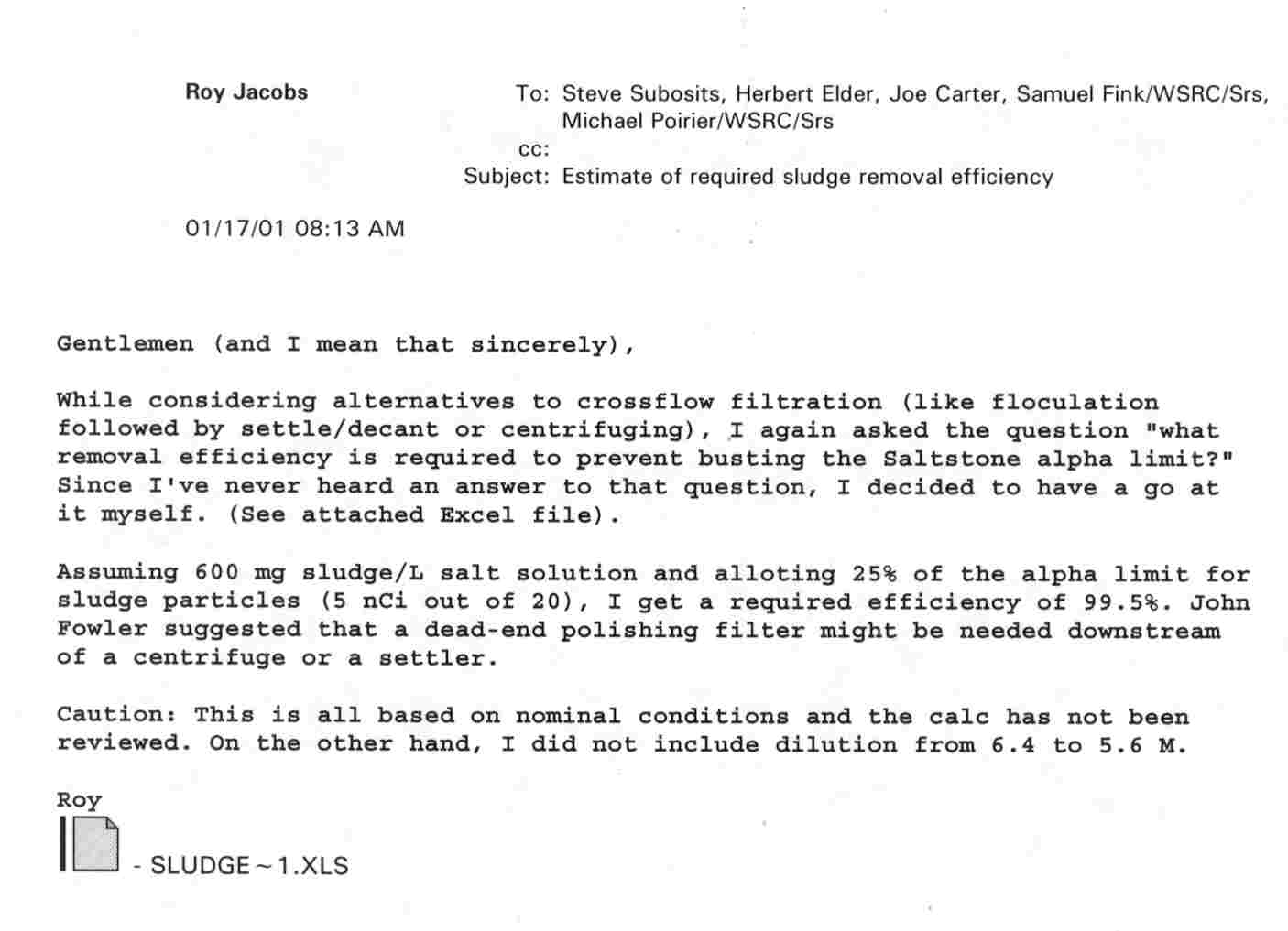
Jacobs estimated the required target removal efficiency for this test as 99.5% (see Attachment 1 for details).12 Since the baseline feed solution contains 1.15 g/L insoluble solids, the clarified product stream should contain less than 0.006 g/L insoluble solids. An insoluble solids concentration of 0.006 g/L corresponds to a turbidity of 5 – 10 NTU.13
Experimental
Apparatus
The Pilot Centrifuge Test Facility centered on an Alfa-Laval Sharples P600 series decanter centrifuge. The facility included a 100-gallon polypropylene slurry feed tank with a Lightnin’Ò Model EV5P50M ½ HP mixer. Clarified liquid product collected in a 150-gallon polypropylene tank, and the solids product collected in a modified 25-L polypropylene carboy. Figure 1 contains a photograph of the pilot test facility. Test slurry was fed to the centrifuge by way of a 3 HP Teel centrifugal pump with variable recycle back to the feed tank. Flow of the feed slurry was controlled manually by a 3/8" metering valve and monitored by a Fischer-Porter 3/8" magnetic flow meter. Data were logged by a computerized data acquisition system (DAS) that consisted of a Dell Dimension XPS T700r desktop computer running LabView version 5.1.
The operating principle behind the decanter centrifuge (see Figure 2) is that denser solids sediment against the rotating bowl wall. The less dense liquid phase forms a concentric inner layer. Personnel can vary the liquid or "pond" depth, with a maximum pond depth preferred for maximum liquid clarification.
The sedimented solid particles continuously exit from the centrifuge bowl by virtue of the action of a helical screw conveyor or "scroll". The scroll rotates at a slower speed than the bowl. The gearbox establishes the differential speed between the scroll and bowl. The solids are pushed out of the pond by the scroll and up the conical "beach". The centrifugal force generated by the rotating centrifuge compacts the solids and expels excess liquid. The concentrated solids discharge from the feed end of the centrifuge and the clarified liquid discharges from the opposite end.
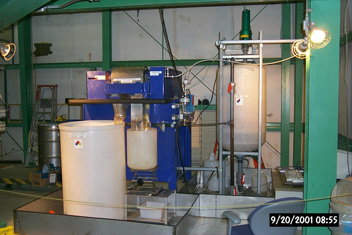
Figure 1. Pilot Centrifuge Test Facility
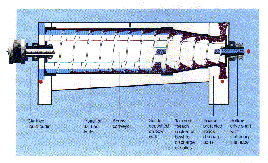
Figure 2. Schematic of Decanter Centrifuge
Feed Slurries
All slurries fed to the centrifuge were made from a stock 5.6 M sodium simulated average SRS High-Level Waste (see Table 1). We omitted sodium chloride and sodium fluoride from the feed at the vendor’s request, to prevent corrosion. Personnel added insoluble solids to the solution in varying amounts. The insoluble solids for the various tests consisted of the following: (1) sim-ulated Tank 8F sludge, (2) simulated Tank 8F sludge and MST, (3) simulated Tank 8F sludge, strontium nitrate and sodium permanganate, and (4) simulated Tank 8F sludge, MST, and Cytec HX-400 flocculant. Table 2 shows the insoluble solids concentration for each test. In the tests with sodium permanganate, researchers added sodium formate as the reducing agent (4.5 moles of formate per mole of manganese). In the flocculant tests, personnel added the flocculant at 15 mg of flocculant per gram of insoluble solids (i.e., 1.5 wt % solids basis).
Previously, SRTC found that the addition of strontium nitrate and sodium permanganate improved strontium and actinide removal from Hanford High Level Waste solutions.14 In addition, they found strontium nitrate and sodium permanganate addition improved cross-flow filtration rates. The researchers performed tests with those additives to evaluate the solid-liquid separation by centrifuge for this alternate process chemistry.
In other testing, SRTC found the addition of flocculants, such as Cytec HX-400, improved particle settling and filtration.13,15 Tests included this additive to evaluate its impact on centrifugation.
Table 1. Centrifuge Test Supernate Composition
|
Species |
Concentration |
|
Na |
5.6 (M) |
|
K |
0.015 (M) |
|
Cs |
0.00014 (M) |
|
OH |
1.93 (M) |
|
NO3 |
2.16 (M) |
|
NO2 |
0.53 (M) |
|
AlO2 |
0.31 (M) |
|
CO3 |
0.16 (M) |
|
SO4 |
0.15 (M) |
|
PO4 |
0.01 (M) |
|
C2O4 |
0.004 (M) |
|
SiO3 |
0.004 (M) |
|
MoO4 |
0.0002 (M) |
|
Tri-n-butyl phosphate |
0.5 mg/L |
|
Di-n-butyl phosphate |
25 mg/L |
|
Mono-n-butyl phosphate |
25 mg/L |
|
n-butanol |
2 mg/L |
|
Formate |
1500 mg/L (0.033 M) |
Table 2. Insoluble Solids Concentration for Centrifuge Tests
|
Sludge + MST |
Sludge Only |
Sludge + MnO4 |
Sludge + MST + Flocculant |
|
0.031 wt % sludge |
0.06 wt % sludge |
0.031 wt % sludge |
0.031 wt % sludge |
|
0.15 wt % sludge |
0.29 wt % sludge |
0.15 wt % sludge |
0.15 wt % sludge |
|
0.67 wt % sludge |
1.29 wt % sludge |
0.67 wt % sludge |
0.67 wt % sludge |
|
3.1 wt % sludge |
6.0 wt % sludge |
|
3.13 wt % sludge |
Experimental Operations
Each experiment began by combining simulated supernate solution and the appropriate amount of solids in the feed tank and agitating the mixture for a minimum of 15 minutes. Then, personnel collected a sample (~ 50 mL) of the feed for later turbidity measurement. Operators started the centrifuge in accordance with EDS Field Procedure FP-904. To achieve maximum liquid clarification, we operated the centrifuge at a maximum differential speed between the bowl and scroll by running the scroll at its minimum speed (approximately 1670 rpm) and running the bowl at its maximum safe operating speed of approximately 5000 rpm (approximately 4100 Gs). According to the following equation, with a gear ratio of 98:1, this condition yields a differential of approximately 34.
D(differential) = [Bowl speed – Scroll speed]/Gear ratio
Once the centrifuge reached the appropriate speed, personnel activated the DAS and then introduced feed. The initial tests used a slurry feed rate of approximately 0.5 gpm, but we later reduced the rate to 0.1 gpm to increase residence time in the centrifuge. Slurry feed to the centrifuge continued for two hours, during which time personnel collected samples of the clarified liquid product (~50 mL) every 15 minutes and analyzed them for turbidity. When the feed was consumed operators closed the feed valve, and stopped the Teel pump.
At the end of each test, personnel collected a concentrated solids product sample. Operators then rinsed the centrifuge with process water until the liquid product stream discharge appeared clear. Personnel shut down the centrifuge according to Field Procedure FP- 904.
Results
Table 3 shows the turbidity of the clarified liquid stream and the estimated insoluble solids concentration calculated from the equation developed by Martino et. al.13 The results show the product turbidity significantly exceeds the target of 5 – 10 NTU. The product from the tests with Tank 8F simulated sludge had a turbidity of 91 ± 41 NTU.
Table 3. Centrifuge Product Turbidity
|
Feed Solids |
Clarified Liquid |
|||||||
|
Sludge (wt%) |
MST (wt%) |
Floc (wt%) |
Sr(NO3)2 (M) |
MnO4 (M) |
Insol. Solids meas. (wt%) |
Turbidity (NTU) |
Samples |
Insol. Solids (mg/L) |
|
0.06 |
- |
- |
- |
- |
< 0.5 |
101.5 ± 21.8 |
9 |
28 |
|
0.29 |
- |
- |
- |
- |
< 0.5 |
68.7 ± 26.3 |
8 |
41 |
|
1.29 |
- |
- |
- |
- |
< 0.5 |
103.6 ± 68.0 |
6 |
42 |
|
6.0 |
- |
- |
- |
- |
Not measured |
|||
|
0.031 |
- |
- |
0.0065 |
0.0065 |
< 0.5 |
227.3 ± 74.5 |
15 |
92 |
|
0.15 |
- |
- |
0.031 |
0.031 |
0.54 |
154.8 ± 24.1 |
9 |
63 |
|
0.67 |
- |
- |
0.14 |
0.14 |
5.5 |
445.1 ± 68.6 |
9 |
180 |
|
0.031 |
0.029 |
- |
- |
- |
< 0.5 |
164.6 ± 19.6 |
9 |
67 |
|
0.15 |
0.14 |
- |
- |
- |
< 0.5 |
392.4 ± 71.1 |
9 |
159 |
|
0.67 |
0.62 |
- |
- |
- |
< 0.5 |
255.0 ± 29.5 |
9 |
103 |
|
0.031 |
0.029 |
0.0009 |
- |
- |
< 0.5 |
32.2 ± 6.9 |
9 |
13 |
|
0.15 |
0.14 |
0.0044 |
- |
- |
< 0.5 |
67.3 ± 10.4 |
9 |
27 |
|
0.67 |
0.62 |
0.019 |
- |
- |
0.80 |
48.1 ± 21.0 |
9 |
19 |
|
3.1 |
2.9 |
0.09 |
- |
- |
3.3 |
51.9 ± 12.5 |
9 |
21 |
The product from the tests with Tank 8F simulated sludge plus MST had a turbidity of 271 ± 105 NTU. The product turbidity with only sludge feed proved lower than the product turbidity with sludge and MST feed.
The product from the tests with Tank 8F simulated sludge plus strontium nitrate and sodium permanganate had a turbidity of 267 ± 130 NTU. The addition of strontium and permanganate led to higher product turbidity.
The product from the tests with Tank 8F simulated sludge plus MST and a polymeric flocculant had a turbidity of 50 ± 18 NTU. The addition of the flocculant improved product quality, but not to the level desired. In previous testing, flocculants showed significant improvement in particle settling rate.13,15 However, in this test, shear from the recirculation pump and agitator probably tended to break down the flocculated solids as also observed in previous cross-flow filter tests.
According to the vendor (Alfa Laval), a 20 gpm decanter centrifuge (model CHNX-418) would be 3.5 m x 1.0 m x 2 m high. A 20 gpm disk centrifuge (model CHPX-513) would be 1.3 m x 1.5 m x 2 m high. The vendor provided a list of 62 units in nuclear service in Europe (see Attachment 2). The units are in research laboratories, power plants, and waste disposal facilities.
Even though it did not achieve the target solids removal, the testing does suggest that a centrifuge could be employed for solid-liquid separation under the following options: a combination of a centrifuge and polishing filter, a two-stage centrifugation system, or no additional treatment following the centrifuge.
The centrifuge reduced the insoluble solids level in the feed stream to 13 – 180 mg/L. This reduction in insoluble solids would slow cake buildup in a cross-flow filter and could increase filter flux. Previous SRTC testing investigated settling and decanting followed by polishing filtration. The tests showed that reducing the insoluble solids in the filter feed could increase cross-flow filter flux significantly.13 Based on the settling study and the results from these tests, we estimate centrifugation as a pretreatment could increase filter flux to 0.25 gpm/ft2. However, a firm estimate requires more thorough testing to quantify the improvement.
Insoluble solids removal could improve with a two-stage centrifugation system. The first stage would use a decanter type centrifuge, such as the one used in this testing. The second stage would use a disk centrifuge, which is more effective at removing small, slow settling particles. To evaluate this option, we could supply product samples from these tests to the vendor to evaluate the feasibility of the two-stage centrifugation process. The vendor recommended this approach.
The level at which insoluble solids adversely impact the centrifugal contactors has not been determined. Hence, another option would feed product samples from these tests to the 2 cm centrifugal contactors to determine whether the solids levels observed in these tests adversely impact them. The authors recommend a set of scouting tests to examine whether the solids collect in the contactors.
Conclusions
The conclusions from this work follow.
Options
The testing does suggest that a centrifuge could be employed for solid-liquid separation under the following options:
References
Attachment 1
Determination of Required Insoluble Solids Removal

Attachment 2
ALFA Laval Centrifuges in European Nuclear Facilities
|
Customer |
Country |
Contractor |
Machine |
Qty. |
Year |
Location |
Type |
|
Euroatom |
Italy |
CRPX 207 SGV |
1 |
1966 |
RL |
Disk |
|
|
RCN, Petten |
Netherlands |
BRPX 213 SFD |
1971 |
WD |
Disk |
||
|
Toshiba |
Japan |
BRPX 213 SGV |
2 |
1975 |
PP |
Disk |
|
|
Coarso |
Italy |
CRPX 207 SGP |
2 |
1978 |
PP |
Disk |
|
|
EIR |
Switzerland |
BRPX 213 SGV |
1 |
1978 |
RL |
Disk |
|
|
Mühlenberg |
Switzerland |
BRPX 207 SGV |
2 |
1978 |
PP |
Disk |
|
|
Benznau |
Switzerland |
BRPX 207 SGV |
1 |
1978 |
PP |
Disk |
|
|
Toshiba |
Japan |
BRPX 213 SGV |
2 |
1980 |
PP |
Disk |
|
|
Toshiba |
Japan |
BRPX 417 SGV |
2 |
1980 |
PP |
Disk |
|
|
Toshiba |
Japan |
BRPX 213 SGV |
2 |
1981 |
PP |
Disk |
|
|
Toshiba |
Japan |
BRPX 417 SGV |
2 |
1981 |
PP |
Disk |
|
|
Toshiba |
Japan |
BRPX 417 SGV |
1 |
1981 |
PP |
Disk |
|
|
KKW Isar 1 |
Germany |
Siemens |
BRPX 213 SGV-34 |
1 |
1981 |
PP |
Disk |
|
KKW Brunsbüttel |
Germany |
Siemens |
BRPX 213 SGV-34 |
1 |
1982 |
PP |
Disk |
|
Nersa |
France |
BRPX 213 SGV |
1 |
1983 |
PP |
Disk |
|
|
KKW Phillipsburg 1 |
Germany |
Siemens |
BRPX 207 SGV-34 |
1 |
1983 |
PP |
Disk |
|
KKW Phillipsburg 1 |
Germany |
Siemens |
BRPX 213 SGV-34 |
1 |
1983 |
PP |
Disk |
|
KKW Phillipsburg 1 |
Germany |
Siemens |
KWNX 416 S-31G |
1 |
1983 |
PP |
Decanter |
|
KKW Phillipsburg 2 |
Germany |
Siemens |
BRPX 213 SGV-34 |
1 |
1983 |
PP |
Decanter |
|
KKW Phillipsburg 2 |
Germany |
Siemens |
KWNX 416 S-31G |
1 |
1983 |
PP |
Decanter |
|
Toshiba |
Japan |
BRPX 413 SGD |
2 |
1983 |
PP |
Disk |
|
|
KKW Isar 2 |
Germany |
Siemens |
BRPX 213 SGV-34 |
1 |
1985 |
PP |
Disk |
|
KKW Isar 2 |
Germany |
Siemens |
KWNX 416 S-31G |
1 |
1985 |
PP |
Decanter |
|
Idreco |
Italy |
BRPX 213 SGV |
3 |
1985 |
PP |
Disk |
|
|
KKW Neckarwestheim |
Germany |
Siemens |
BRPX 213 SGV-34 |
1 |
1985 |
PP |
Disk |
|
KKW Neckarwestheim |
Germany |
Siemens |
KWNX 416 S-31G |
1 |
1985 |
PP |
Decanter |
|
KKW Brockdorf |
Germany |
Siemens |
BRPX 213 SGV-34 |
1 |
1985 |
PP |
Disk |
|
KKW Brockdorf |
Germany |
Siemens |
KWNX 416 S-31G |
1 |
1985 |
PP |
Decanter |
|
KKW Emsland |
Germany |
Siemens |
BRPX 213 SGV-34 |
1 |
1985 |
PP |
Disk |
|
KKW Emsland |
Germany |
Siemens |
KWNX 416 S-31G |
1 |
1985 |
PP |
Decanter |
|
KKW Obrigheim |
Germany |
BRPX 213 SGV-34 |
1 |
1986 |
PP |
Disk |
|
|
KKW Obrigheim |
Germany |
KWNX 416 S-31G |
1 |
1986 |
PP |
Decanter |
|
|
KKW Würgassen |
Germany |
BRPX 213 SGV-34 |
2 |
1987 |
PP |
Disk |
|
|
KKW Karlstein |
Germany |
NX 309 |
1 |
1987 |
RL |
Decanter |
|
|
KKW Grohnde |
Germany |
CHPX 510 SGD-34 CG |
1 |
1990 |
PP |
Disk |
|
|
KKW Grohnde |
Germany |
KWNX 416 S-31G |
1 |
1990 |
PP |
Decanter |
|
|
KKW Phillipsburg 1 |
Germany |
Siemens |
CHPX 510 SGD-34 CG |
1 |
1990 |
PP |
Disk |
|
KKW Phillipsburg 1 |
Germany |
Siemens |
KWNX 416 S-31G |
1 |
1990 |
PP |
Decanter |
|
KKW Karlstein |
Germany |
KWNX 409 S-31G |
1 |
1992 |
RL |
Decanter |
|
|
KKW Isar 1 |
Germany |
BRPX 213 SGV-34 CG |
1 |
1992 |
PP |
Disk |
|
|
ABB Atom |
Sweden |
KWNX 416 |
1 |
1994 |
PP |
Decanter |
|
|
KKW Rheinsberg |
Germany |
Siemens |
KWNX 416 |
1 |
1995 |
PP |
Decanter |
|
Teollisuuden Voima Oy |
Finnland |
KWNX 416 |
1 |
1995 |
PP |
Decanter |
|
|
Teollisuuden Voima Oy |
Finnland |
CHPX 510 |
1 |
1995 |
PP |
Disk |
|
|
Sage Brno (Temelin) |
Czech Rep. |
KWNX 418 |
1 |
1996 |
PP |
Decanter |
|
|
Sage Brno (Temelin) |
Czech Rep. |
CHPX 513 |
1 |
1996 |
PP |
Disk |
|
|
Teollisuuden Voima Oy |
Finnland |
KWNX 416 |
1 |
1996 |
PP |
Decanter |
|
|
Teollisuuden Voima Oy |
Finnland |
CHPX 510 |
1 |
1996 |
PP |
Disk |
|
|
Zwilag Würenlingen |
Switzerland |
BWB |
BTPX 205 SGD-34 CDP |
1 |
1997 |
WD |
Disk |
|
Yonggwang 5 |
Korea |
HPA |
CHPX 517 SGV-34 CGR |
1 |
1997 |
PP |
Disk |
|
Yonggwang 5 |
Korea |
HPA |
KWNX 418 S-31 |
1 |
1997 |
PP |
Decanter |
|
Yonggwang 6 |
Korea |
HPA |
CHPX 517 SGV-34 CGR |
1 |
1997 |
PP |
Disk |
|
Yonggwang 6 |
Korea |
HPA |
KWNX 418 S-31 |
1 |
1997 |
PP |
Decanter |
|
62 |
|||||||
|
Key to location: |
RL |
Research lab |
|||||
|
PP |
Power Plant |
||||||
|
WD |
Waste disposal |