WSRC-TR-2001-00438, Rev. 1
Functions and Requirements for the Leak Mitigation
System of the Savannah River Site Double
Shell High Level Waste Tanks
K. H. Subramanian and B. J. Wiersma
Westinghouse Savannah River Company
Aiken, SC 29808
This report was prepared as an account of work sponsored by an agency of the United States Government. Neither the United States Government nor any agency thereof, nor any of their employees, makes any warranty, express or implied, or assumes any legal liability or responsibility for the accuracy, completeness, or usefulness of any information, apparatus, product or process disclosed, or represents that its use would not infringe privately owned rights. Reference herein to any specific commercial product, process or service by trade name, trademark, manufacturer, or otherwise does not necessarily constitute or imply its endorsement, recommendation, or favoring by the United States Government or any agency thereof. The views and opinions of authors expressed herein do not necessarily state or reflect those of the United States Government or any agency thereof.
This report has been reproduced directly from the best available copy.
Available for sale to the public, in paper, from: U.S. Department of Commerce, National Technical Information Service, 5285 Port Royal Road, Springfield, VA 22161, phone: (800) 553-6847, fax: (703) 605-6900, email: orders@ntis.fedworld.gov online ordering: http://www.ntis.gov/support/index.html
Available electronically at http://www.osti.gov/bridge
Available for a processing fee to U.S. Department of Energy and its contractors, in paper, from: U.S. Department of Energy, Office of Scientific and Technical Information, P.O. Box 62, Oak Ridge, TN 37831-0062, phone: (865 ) 576-8401, fax: (865) 576-5728, email: reports@adonis.osti.gov
Acronym List
|
ALARA |
As Low As Reasonably Achievable |
|
DOE |
Department of Energy |
|
DST |
Double Shell Waste Tank |
|
ID |
Inner Diameter |
|
NFPA |
National Fire Protection Association |
|
OSHA |
Occupational Safety and Health Administration |
|
PDT |
Performance Demonstration Test |
|
PNNL |
Pacific Northwest National Laboratory |
|
R/hr |
Roentgen/hour |
|
SRS |
Savannah River Site |
|
SST |
Single-Shell Waste Tank |
|
TSR |
Technical Safety Requirement |
|
TRRS |
Tank Remote Repair System |
|
UPS |
Uninterruptible Power Supply |
|
VAC |
Volts (Alternating Current) |
|
WSRC |
Westinghouse Savannah River Company |
1. Introduction
1.1 Background
The Savannah River Site (SRS) High Level Waste (HLW) storage tanks have been in service for 20 to 45 years. Degradation evaluations of DOE HLW tanks conclude that pitting and stress corrosion cracking are two primary degradation modes for the carbon steel tanks in extended service. The SRS HLW tank service experience has been that some of the tanks have suffered stress corrosion cracking that led to leakage failures. In comparison, Hanford Double-Shell Tank experience has been instances of pitting.
Of the 16 total Types I and II tanks at SRS, 11 have leaked into the annular space, including all four Type II tanks. Laboratory testing has shown that the leaksites were caused by nitrate stress-corrosion cracking (SCC). Field examinations of the tanks, and laboratory testing & analysis, has shown that the cracking is confined to the residual stress field of the fabrication and repair welds. Chemistry control for HLW was developed and instituted at SRS in the late 1970’s to prevent the further initiation of cracking and to avoid initiation of pitting. However, what are assumed to be pre-existing stress corrosion cracks, not observed through visual examination, have been found to contribute to leakage in the re-use of several of these tanks. A leak mitigation/crack-sealing system would allow for continued storage and planned retrieval operation without additional leakage into the secondary pans. This document provides the basis for the functions and requirements of a proposed leak mitigation system (LMS) for HLW tanks.
1.2 Description
This document defines the functions and requirements for a leak mitigation system applicable to leaksites found in HLW tanks.
1.3 Purpose
The purpose of this document is to provide criteria for the selection of a LMS concept and the design, fabrication, and application methodology. The document provides the specifications for materials engineered, procured, and applied for leak mitigation from stress-corrosion cracks and pitting found in HLW tanks. Auxiliary documents will be referenced for appropriate use as additional technical bases.
1.4 Scope
This document defines the functions and requirements for a LMS applicable to leaksites caused by cracking or pitting found in HLW tanks. The scope of this document includes the following: (1) a description of the leak phenomenon (2) intended use of the selected leak mitigation system, and (3) evaluation criteria for concept, design, fabrication, and application strategy.
1.5 Definitions
Assumption: An assumption is the basis for a requirement that is taken to be true without necessarily having proof or demonstration. Changes in assumptions may have significant impacts on related requirements.
Function: A function is a description of the task that a system, subsystem, or component must perform. It is not a description of the device in any manner, but may establish some of the parameters governing the overall geometry of the device.
Requirement: A requirement is a mandatory factor that must be applied or incorporated into the design of the device performing the specified function. It is not a preference and uses the word shall.
2. General Assumptions, Functions, and Requirements
2.1 Assumptions
2.1.1 General
The LMS will be applied using a tank remote repair system (TRRS). This repair system will be remotely controlled and deployed through the tank risers. The F&R for the TRRS is under development under TTP SR10C131. The LMS will be viewable during application from a remote inspection camera.
2.1.2 Application Strategy
The LMS will be applied only to the primary tank wall, by a method yet to determined. The method will be dependent upon the LMS determined to be most effective through experimental testing.
The LMS must be applicable while continuing routine operations. The LMS must be applicable throughout the primary liner of the tank within the accessibility range of the TRRS. Ultimately, the LMS must be applicable to an active leaksite.
2.1.3 Ancillary Equipment
The materials for LMS can be applied from a central source outside the HLW tanks through an umbilicus, or have limited storage on the TRRS.
2.1.4 Control Center
All control equipment must be portable to allow for quick setup, movement, and recharging/refilling of appropriate materials. The equipment may be operated outdoors, but will be protected from inclement weather via a temporary shelter.
2.1.5 Power
The LMS shall not require power for functionality.
2.1.6 Interfaces
The system controls will interface with all components and subsystems. The LMS must be compatible in all components of the TRRS and shall not hamper its function.
2.2 Functions
2.2.1 Function Summary
The function of the LMS is to mitigate observed leaks from the primary tank walls in the Type I and Type II High Level Waste double shell tanks. The LMS is the material used to ultimately stop any leaks due to active/formerly active degradation mechanisms, for a finite time period to be defined
2.2.2 Complement Functions
2.2.2.1 Surface Preparation (SP)
The SP function will be to ensure that the exterior of the tank wall will be adequately prepared for successful application of the LMS. The TRRS will be responsible for the surface preparation. The demonstration testing for the LMS will consider the extent of surface preparation necessary as a variable for selection criteria. HLW tanks have been found to have minimal amounts of minor scale and rust from service. The self-sealing process deposited salt nodules on the primary tank wall that may have to be removed prior to LMS application to ensure adequate surface preparation.
2.2.2.2 Leak Sealing
The function of the LMS will be to mitigate leaks associated with the degradation mechanisms in HLW tanks. Leak sealing is to be defined as "zero leakage" for a finite time period to be developed. It is anticipated that the time period will be coincidental with waste removal operations. "Zero Leakage" shall be defined as leakage from the particular leaksite on the primary tank liner to which the LMS is applied.
2.3 Requirements
2.3.1 Modular Design
Each application of the LMS will be a unique application. The material need not be retrievable, but the LMS must be developed to repair past applications.
2.3.2 Maintainability
LMS components that have a higher probability of failure during the application process shall be mounted on fixtures that can easily be removed for servicing. The LMS will be used within the time-frame of the shelf-life.
2.3.3 Availability
Materials chosen for this project shall be commercial as much as practical.
2.3.4 Suitability
The LMS shall be selected/developed on the basis of several selection criteria. These will include, but are not limited to the following: (1) mechanical stability, (2) chemical resistance, (3) radiation resistance, (4) ease of application, (5) reliability, (6) impact to routine operations, and (7) intended design life.
2.3.5 Safety
Protection of the public, the system and site operators, the environment and the equipment supercede all other functions and requirements. A listing of applicable regulations and governing documents is provided in Section 5.0. The LMS shall adhere to ALARA principles by limiting worker and environmental exposure to radiological materials, reducing the volume of secondary wastes, minimizing external contamination, and incorporating design features to ease maintenance of contaminated components. The safety classification for the LMS will Production Support (PS).
2.3.6 Quality
All equipment will be fabricated in accordance with SRS quality assurance requirements. Research and development will be conducted in accordance with SRS E.7 Manual, "Conduct of Engineering and Technical Support".
2.3.7 Lifting and Hoisting
All hardware associated with lifting and hoisting and/or rigging for hoisting shall conform to WSRC-TM-90-7 "SRS Hoisting and Rigging Manual" and DOE-STD-1090-9 "DOE Hoisting and Rigging Standard".
2.3.8 Failure of System
The LMS shall not incorporate components whose failure could cause damage to the HLW tank or prevent removal of the system from the annulus. The LMS shall be qualified for use in the HLW tanks prior to application. The qualification of the LMS shall ensure that waste processing/waste removal operations shall not be affected.
2.3.9 Environmental Conditions
The LMS must be able to survive during the following environmental conditions:
2.3.9.1 Waste Tank Annulus
2.3.9.1.1 Temperature and Humidity
The air temperature in the waste tank annulus ranges from 50 to 200 degrees Fahrenheit. The primary tank wall is the heat source and can reach 200 degrees Fahrenheit but is maintained above 70 degrees Fahrenheit. The air temperature decreases axially further way from the tank wall. The tank annulus space ranges from 5 to 95% relative humidity.
2.3.9.1.2 Radiation
The radiation field in the waste tank annulus ranges from 0 to 1000R/hr. The LMS shall be designed to withstand the cumulative radiation field throughout the intended design life maintaining "zero leakage".
2.3.9.1.3 Addition of Water
The LMS shall be designed such that any fluid additions will be adequately retrievable without adversely affecting waste processing/waste retrieval operations. Any fluid additions shall be made only after approval.
2.3.9.2 Outside Conditions
All equipment that is outside of the waste tank annulus shall be capable of operating in temperature extremes from 10 degrees Fahrenheit to 120 degrees Fahrenheit and 5-95% relative humidity.
2.3.10 Retrievable
Once applied, the LMS need not be retrievable from the primary tank liner. If degraded and found in the annulus region, it shall be retrievable.
2.3.11 Storage
The LMS will be stored only for its defined shelf-life.
3. Specific Requirements for the LMS
3.1 Description
The LMS will be used to mitigate leaks from HLW tanks. A completely leak-tight repair will be defined as "zero leakage" for a finite time period to be determined on a case-by-case basis.
3.2 High Level Waste Tanks
3.2.1 Materials and Structure
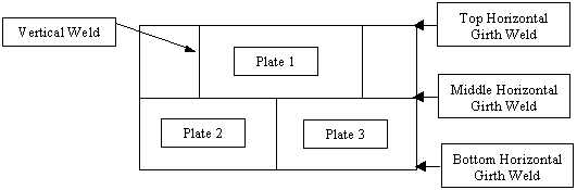
The SRS Types I and II HLW tanks were made of low carbon steel. The tanks are constructed with a top weld to the top of the tank, middle welds between plates, and bottom welds to the bottom of the plate. The fabrication welds include vertical welds between plates. A 5-foot high pan provides secondary containment for the tanks and a concrete vault encompassing the primary tank provides another barrier between the primary tank and the ground. Single-butt girth welds join each of the plates, and none of the Types I and II tanks was stress-relieved.
3.2.2 Degradation Mechanisms
3.2.2.1 Stress Corrosion Cracking
Stress corrosion cracking (SCC) has been the principal degradation mechanism for the primary liner in waste storage tanks that have not been stress-relieved. The cracks are perpendicular to the butt welds and extend through the residual stress field. Research and analysis of trephined specimens from decommissioned tanks has shown that the cracks were due to nitrate induced intergranular stress corrosion cracking (IGSCC). In addition, residual stress fields induced by repair welds also provide the tensile stress necessary for IGSCC to occur.
3.2.2.2 Pitting
No significant pitting of the primary or secondary liner has occurred during waste storage operations. However, pits have been observed in various tanks during construction. It was determined that the pitting mechanism involved oxygen concentration cells that formed in crevices created by the protective plywood placed on the floor of the tanks. It was determined that the pitting did not compromise the integrity of the tanks. Chemistry control of the bulk waste has established conditions in which pits no longer initiate.
3.2.3 Leaksite Analysis
The LMS will be used to mitigate leaks from stress corrosion cracks and pits, if the exact location of the pits are known. A schematic of the waste tank fabrication welds is shown in Figure 1. A schematic of the location of the stress corrosion cracks with respect to welds is shown in Figure 2. Waste leakage through stress corrosion cracks typically deposit a salt nodule on the primary tank wall. These salt nodules are ultimately indicative of and responsible for the stabilization and "self-sealing" of the leak site. Self-sealing occurs when the water from the leaking waste evaporates due to the annulus ventilation and the salt is deposited on the tank wall. Thus the self-sealing rate is dependent upon the competition of leakage rate with evaporation rate due to annulus ventilation.
Figure 1. Weld Pattern for HLW Tanks
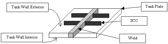
Figure 2. Fabrication Weld with SCC Schematic
3.3 LMS Material Specifications
The materials to be used for the LMS may be qualified for use in the HLW tank farm in accordance with waste acceptance criteria, for minimal influx of material into the primary tank. Currently, waste acceptance criteria are included in "CST TSR Administrative Control Compliance Requirements" (G-TRT-G-00003, Rev. 38, 3/01). However, the applicability of the material used for the LMS may be limited to application on the exterior of the primary tank liner and so designed that there is no influx of material into the primary tank.
3.4 Intended Design Life
The LMS shall be effective throughout the intended life and use of the tank to which it is applied. The material shall adhere to the tank wall permanently without extensive degradation that could lead to the large buildup of LMS material in the annulus.
3.5 Post Application Effects
The application of the LMS shall not have a detrimental effect on the In-Service Inspection Program. The LMS shall be integrated into the in-service inspection plan when appropriate. The LMS shall be inspectable when in service. In addition, the LMS must leave the steel tank wall beneath inspectable via ultrasonic or visual testing. (UT, VT) The LMS shall not degrade the carbon steel material to which it is applied. The LMS shall not contribute to the buildup of flammable vapor within the annular space.
4. LMS Testing and Demonstration
4.1 Selection Testing
Selection testing of the LMS shall be performed to demonstrate proper operation and performance. Testing prerequisites will ensure that the LMS is set up and operational. All testing conditions will be reflective of the actual waste tanks. The mechanical stability, chemical resistance, radiation resistance shall be three integral parameters in the selection criteria.
4.2 Test Plan and Procedures
A test plan shall be developed for testing and selection of the LMS. The test plan shall identify all necessary equipment, procedures, and conditions for completing the test including: (1) chemistry, (2) crack or pit configuration, (3) test plate material, condition, and thickness, and (4) acceptance criteria for zero leakage at test conditions.
4.3 LMS Demonstration Tests
The LMS shall be applied to the primary tank wall mock-up containing real or simulated leaksites. Operation of the LMS, leaksite sealing, and consequent measurements to confirm "zero leakage" shall be demonstrated at the selected test conditions.
4.4 Test Reports
A test report of the results of the selection testing and demonstration testing will be published.
5. References
5.1 Governing Site Safety Documents
WSRC 8Q Employee Safety Manual5.2 Applicable Codes and Standards
WSRC 18Q Safe Electrical Practices & Procedures
CST TSR Administrative Control Compliance Requirements (G-TRT-G-00003, Rev. 38, 3/01)
5.3 Fire Protection
WSRC 2Q Fire Protection Program Manual
NFPA 70-93, National Electric Code, National Fire Protection Association, Batterymarch Park, Massachusetts, 1993.
NFPA 101-91, Life Safety Code, National Fire Protection Association, Batterymarch Park, Massachusetts, 1991.
5.4 Design
WSRC E7, Conduct of engineering and Technical Support
WSRC-IM-95-58, SRS Engineering Practices Manual
5.5 Inspection
SNT-TC-1A 1996, American Society for Nondestructive Testing, Columbus, Ohio