WSRC-TR-2001-00373
Salt Waste Processing Pilot Facility Feed Basis for Design
J. A. Pike
Westinghouse Savannah River Company
Aiken, SC 29808
This report was prepared as an account of work sponsored by an agency of the United States Government. Neither the United States Government nor any agency thereof, nor any of their employees, makes any warranty, express or implied, or assumes any legal liability or responsibility for the accuracy, completeness, or usefulness of any information, apparatus, product or process disclosed, or represents that its use would not infringe privately owned rights. Reference herein to any specific commercial product, process or service by trade name, trademark, manufacturer, or otherwise does not necessarily constitute or imply its endorsement, recommendation, or favoring by the United States Government or any agency thereof. The views and opinions of authors expressed herein do not necessarily state or reflect those of the United States Government or any agency thereof.
This report has been reproduced directly from the best available copy.
Available for sale to the public, in paper, from: U.S. Department of Commerce, National Technical Information Service, 5285 Port Royal Road, Springfield, VA 22161, phone: (800) 553-6847, fax: (703) 605-6900, email: orders@ntis.fedworld.gov online ordering: http://www.ntis.gov/support/ordering.htm
Available electronically at http://www.osti.gov/bridge/
Available for a processing fee to U.S. Department of Energy and its contractors, in paper, from: U.S. Department of Energy, Office of Scientific and Technical Information, P.O. Box 62, Oak Ridge, TN 37831-0062, phone: (865 ) 576-8401, fax: (865) 576-5728, email: reports@adonis.osti.gov
Abstract
This paper presents the characterization of potential feed to the Salt Waste Processing Facility (SWPF) pilot facility for design purposes and supercedes any previous representations of feed to the pilot facility.
Keywords: Salt alternatives, Pilot Facility
1. Introduction
Salt Waste Processing Facility (SWPF) pilot facility feed stream will vary from the full-scale facility feed for two reasons. First, the feed will come in part from supernates in individual waste tanks rather than blends of supernates from multiple tanks or dissolved salt cake. Second, the purpose of the pilot facility includes testing the operating bounds of the process. In other words, the feed to the pilot facility is expected to include feed material beyond the range of concentration for important components in feed to the full-scale facility. This paper presents the characterization of potential feed to pilot facility for design purposes and supercedes any previous representations of feed to the pilot facility. Any revisions to the expected feed to the pilot will be represented by revisions to this document.
2. Approach
The pilot facility will operate in phases: water runs, simulated waste runs, traced simulated waste runs, and real waste runs.1 The facility will process radionuclides during traced simulated waste runs, and real waste runs. The simulated wasted used during the simulated waste runs and traced simulated waste runs is the same. The chemical characteristics processed during traced runs are already provided and is repeated here for convenience.2
Chemical and radionulide characterizations are provided separately. Average feed material is presented along with maximum concentrations. Individual components are analyzed for average and maximum so that the resulting mixture may not represent an actual waste solution transferred, but the extremes of the individual components.
Radionuclide concentrations for supernate in each waste tank are extracted from the HLW Waste Characterization System (WCS). Since the sodium concentration varies up to 15 M among the waste tanks, the radionuclide data are adjusted to solutions at 6.44 M total sodium concentration. The sodium concentration in actual material transferred as feed will change from existing concentrations due to in-transfer dilution.
The radionuclide contribution of the entrained sludge is estimated from the average distribution of radionuclides in HLW sludge, which is extracted from the WCS. The radionuclide contribution of sludge is then calculated by multiplying the mass-based distribution by the design rate of 600 and 1200 mg of sludge solids per liter of solution for average and high values respectively. The sludge contribution is then added to the supernate contribution estimated above.
Chemical characterization is determined by a similar method as the radionuclide concentrations. The anion and metal concentrations is extracted from WCS and minimum, average, and maximum concentrations determined. Chemical concentrations were not adjusted to a standard 6.44 M total sodium feed in order to reflect the variability of the feed material.
The concentrated supernates in many of the tanks is much higher total sodium concentration than dissolved salt cake diluted to 6.44 M total sodium. As such, the maximum radionuclide and chemical concentrations determined by this method will bound the concentrations of any dissolved salt cake.
The maximum annual pilot facility waste processed is assumed to be equivalent to 0.175 gpm waste feed rate at 6.44 M total sodium concentration.
3. Simulated Waste
The chemical characterization of simulated waste solutions is shown in Table 1.
The densities of the three types of salt solution have been measured and the required mass of water can be calculated. The density (g/mL) at 22°C is calculated from the total sodium ion concentration (molar) by the following equations.3
Average: d = 1.009 + 0.04454[Na+]
High hydroxide: d = 1.003 + 0.04302[Na+]
High nitrate d = 1.006 + 0.04725[Na+]
Table 1. Composition of Simulated Waste Solutions2
|
Concentration (molar) |
|||
|
Component |
Average |
High OH- |
High NO3- |
|
Na+ |
5.6 |
5.6 |
5.6 |
|
K+ |
0.015 |
0.030 |
0.0041 |
|
Cs+ |
0.00014 |
0.00037 |
0.00014 |
|
OH- |
1.91 |
3.05 |
1.17 |
|
NO3- |
2.14 |
1.10 |
2.84 |
|
NO2- |
0.52 |
0.74 |
0.37 |
|
AlO2- |
0.31 |
0.27 |
0.32 |
|
CO32- |
0.16 |
0.17 |
0.16 |
|
SO42- |
0.15 |
0.030 |
0.22 |
|
Cl- |
0.025 |
0.010 |
0.040 |
|
F- |
0.032 |
0.010 |
0.050 |
|
PO43- |
0.010 |
0.008 |
0.010 |
|
C2O42- |
0.008 |
0.008 |
0.008 |
|
SiO32- |
0.004 |
0.004 |
0.004 |
|
MoO42- |
0.0002 |
0.0002 |
0.0002 |
4. Traced Simulated Waste
Traced simulated waste contains the same chemical simulant solutions as described earlier with the addition of radioactive tracers. The tracers will be 10 L of real waste supernate as described under the next section.
5. Real Waste
5.1 Radionuclide Characterization
Waste tanks with transferable supernate include Tanks 4, 7, 8, 11, 13, 25 through 39, and 41 through 47. Transferable supernate includes any free aqueous solutions above the installed transfer jet or pump suction and generally above any sludge or salt cake layer. Tanks 40 and 48 through 51 are excluded from consideration as sludge processing and In-Tank Precipitation process tanks. Tanks 18, 19, and 21 through 24 contain very dilute wastes that are not expected to be used as feed.1 These tanks contain Defense Waste Processing Facility (DWPF) recycle and Receiving Basin for Off-Site Fuels (RBOF) wastes. Tanks 1, 2, 3, 9, 10, 12, 14, 15, and 16 do not contain transferable supernate. Tanks 5 and 6 were recently "re-wetted". These tanks were sitting dormant and free of supernate for much longer than 10 years. Initial influents included inhibited water followed by waste transfers to the tanks from else where in the tank farm. The characterization of this waste was not completely incorporated in WCS at the time of this evaluation. Since this waste came from other tanks, it will be bound by the existing analysis if picked to feed the pilot facility.
Table 2 shows the radionuclide distribution and supernate volume extracted from the HLW Waste Characterization System and adjusted to 6.44 M total sodium.
Table 2. Radionuclide Content in Waste Supernate (Ci/gal) by Waste Tank at 6.44 M Total Sodium Concentration
|
Tank |
4 |
7 |
8 |
11 |
13 |
25 |
26 |
27 |
28 |
29 |
30 |
31 |
32 |
|
Cs-137 |
8.65E+00 |
2.32E+00 |
3.34E-01 |
6.13E-01 |
7.11E+00 |
2.33E+00 |
4.72E+00 |
2.02E+00 |
2.32E+00 |
5.19E+00 |
2.91E+00 |
5.76E+00 |
3.45E+00 |
|
Ba-137m |
8.18E+00 |
2.20E+00 |
3.16E-01 |
5.80E-01 |
6.72E+00 |
2.20E+00 |
4.47E+00 |
1.91E+00 |
2.19E+00 |
4.91E+00 |
2.75E+00 |
5.45E+00 |
3.26E+00 |
|
Th-232 |
- |
- |
- |
1.00E-11 |
2.88E-10 |
- |
- |
- |
- |
3.45E-10 |
4.49E-10 |
2.73E-10 |
- |
|
U-232 |
1.05E-09 |
3.12E-10 |
7.35E-10 |
1.18E-13 |
8.18E-11 |
1.89E-09 |
2.38E-09 |
1.73E-09 |
1.80E-09 |
9.82E-11 |
1.28E-10 |
7.77E-11 |
- |
|
U-233 |
- |
- |
- |
1.43E-09 |
5.89E-08 |
- |
- |
- |
- |
7.08E-08 |
9.20E-08 |
5.60E-08 |
- |
|
U-234 |
- |
- |
- |
1.17E-09 |
8.31E-09 |
- |
- |
- |
- |
9.99E-09 |
1.30E-08 |
7.90E-09 |
2.34E-08 |
|
U-235 |
1.12E-09 |
1.35E-09 |
1.67E-09 |
2.22E-11 |
2.27E-10 |
4.22E-09 |
5.32E-09 |
3.87E-09 |
4.04E-09 |
2.73E-10 |
3.55E-10 |
2.16E-10 |
3.35E-10 |
|
U-236 |
- |
- |
- |
1.82E-10 |
8.57E-10 |
- |
- |
- |
- |
1.03E-09 |
1.34E-09 |
8.14E-10 |
5.26E-09 |
|
U-238 |
4.83E-08 |
3.27E-08 |
7.68E-08 |
4.11E-11 |
2.66E-09 |
3.86E-07 |
4.86E-07 |
3.53E-07 |
3.69E-07 |
3.19E-09 |
4.15E-09 |
2.52E-09 |
1.58E-10 |
|
Np-237 |
4.31E-08 |
3.00E-08 |
3.49E-08 |
7.75E-10 |
2.14E-08 |
- |
- |
- |
- |
2.57E-08 |
3.34E-08 |
2.03E-08 |
9.70E-09 |
|
Pu-238 |
8.75E-06 |
8.67E-05 |
1.40E-04 |
1.09E-04 |
8.17E-05 |
3.20E-03 |
4.03E-03 |
2.93E-03 |
3.06E-03 |
9.81E-05 |
1.27E-04 |
7.76E-05 |
3.52E-03 |
|
Pu-239 |
8.64E-06 |
1.31E-05 |
2.19E-05 |
1.04E-06 |
2.12E-06 |
4.57E-04 |
5.76E-04 |
4.18E-04 |
4.37E-04 |
2.54E-06 |
3.30E-06 |
2.01E-06 |
2.98E-05 |
|
Pu-240 |
1.93E-06 |
3.13E-06 |
5.16E-06 |
6.54E-07 |
8.75E-07 |
1.02E-04 |
1.29E-04 |
9.34E-05 |
9.76E-05 |
1.05E-06 |
1.37E-06 |
8.31E-07 |
2.22E-05 |
|
Pu-241 |
2.01E-05 |
2.76E-05 |
6.05E-05 |
4.62E-05 |
1.90E-05 |
2.74E-03 |
3.45E-03 |
2.51E-03 |
2.62E-03 |
2.28E-05 |
2.96E-05 |
1.80E-05 |
1.87E-03 |
|
Pu-242 |
3.97E-10 |
1.01E-09 |
6.51E-09 |
1.39E-09 |
5.81E-10 |
2.10E-08 |
2.65E-08 |
1.92E-08 |
2.01E-08 |
6.97E-10 |
9.06E-10 |
5.52E-10 |
4.67E-08 |
|
Am-241 |
1.65E-04 |
5.00E-05 |
1.11E-04 |
9.05E-06 |
2.72E-05 |
9.19E-05 |
1.16E-04 |
8.41E-05 |
8.78E-05 |
3.27E-05 |
4.25E-05 |
2.59E-05 |
2.16E-04 |
|
Am-242m |
2.11E-07 |
5.74E-08 |
1.38E-07 |
5.97E-09 |
2.93E-08 |
- |
- |
- |
- |
3.52E-08 |
4.58E-08 |
2.79E-08 |
1.23E-07 |
|
Cm-244 |
4.95E-08 |
9.54E-09 |
3.14E-08 |
3.64E-08 |
7.04E-08 |
3.97E-08 |
5.00E-08 |
3.63E-08 |
3.79E-08 |
8.46E-08 |
1.10E-07 |
6.69E-08 |
8.94E-07 |
|
Cm-245 |
3.48E-14 |
1.03E-14 |
2.33E-14 |
3.81E-12 |
8.68E-12 |
1.56E-14 |
1.97E-14 |
1.43E-14 |
1.49E-14 |
1.04E-11 |
1.35E-11 |
8.25E-12 |
7.58E-11 |
Table 2. Radionuclide Content in Waste Supernate (Ci/gal) by Waste Tank at 6.44 M Total Sodium Concentration (continued)
|
Tank |
33 |
34 |
35 |
36 |
37 |
38 |
39 |
41 |
42 |
43 |
44 |
45 |
46 |
47 |
|
Cs-137 |
2.09E-01 |
2.08E+00 |
7.83E+00 |
1.06E+01 |
7.69E+00 |
1.88E+00 |
2.32E+00 |
1.34E+00 |
3.66E-01 |
4.56E-01 |
2.42E+00 |
2.43E+00 |
4.29E+00 |
2.01E+00 |
|
Ba-137m |
1.97E-01 |
1.97E+00 |
7.41E+00 |
1.00E+01 |
7.28E+00 |
1.78E+00 |
2.19E+00 |
1.27E+00 |
3.47E-01 |
4.32E-01 |
2.29E+00 |
2.30E+00 |
4.06E+00 |
1.90E+00 |
|
Th-232 |
- |
- |
- |
2.73E-10 |
2.73E-10 |
- |
- |
- |
6.03E-08 |
- |
- |
- |
- |
- |
|
U-232 |
9.65E-08 |
2.78E-08 |
- |
7.77E-11 |
7.77E-11 |
- |
- |
- |
3.30E-10 |
- |
1.59E-09 |
1.69E-09 |
1.74E-09 |
2.62E-09 |
|
U-233 |
- |
- |
- |
5.60E-08 |
5.60E-08 |
- |
- |
- |
8.49E-07 |
- |
- |
- |
- |
- |
|
U-234 |
- |
- |
9.09E-08 |
7.90E-09 |
7.90E-09 |
1.51E-06 |
2.24E-08 |
1.61E-07 |
3.12E-07 |
3.11E-07 |
- |
- |
- |
- |
|
U-235 |
1.14E-07 |
2.61E-08 |
1.58E-09 |
2.16E-10 |
2.16E-10 |
1.53E-08 |
3.28E-10 |
1.62E-09 |
7.37E-09 |
3.14E-09 |
3.56E-09 |
3.78E-09 |
3.89E-09 |
5.86E-09 |
|
U-236 |
- |
- |
2.68E-08 |
8.14E-10 |
8.14E-10 |
2.31E-07 |
5.28E-09 |
2.45E-08 |
4.18E-08 |
4.75E-08 |
- |
- |
- |
- |
|
U-238 |
1.04E-05 |
1.84E-06 |
9.32E-10 |
2.52E-09 |
2.52E-09 |
2.14E-09 |
2.49E-11 |
2.28E-10 |
1.29E-07 |
4.41E-10 |
3.25E-07 |
3.46E-07 |
3.55E-07 |
5.35E-07 |
|
Np-237 |
8.61E-06 |
1.42E-06 |
3.29E-08 |
2.03E-08 |
2.03E-08 |
1.32E-06 |
8.91E-09 |
1.40E-07 |
2.57E-07 |
2.72E-07 |
- |
- |
- |
- |
|
Pu-238 |
- |
- |
1.41E-02 |
7.76E-05 |
7.76E-05 |
4.17E-02 |
3.59E-03 |
4.43E-03 |
4.31E-03 |
8.57E-03 |
2.70E-03 |
2.87E-03 |
2.95E-03 |
4.44E-03 |
|
Pu-239 |
1.25E-03 |
2.98E-04 |
1.10E-04 |
2.01E-06 |
2.01E-06 |
1.28E-04 |
3.31E-05 |
1.36E-05 |
1.45E-04 |
2.64E-05 |
3.85E-04 |
4.09E-04 |
4.21E-04 |
6.34E-04 |
|
Pu-240 |
2.80E-04 |
6.65E-05 |
8.42E-05 |
8.31E-07 |
8.31E-07 |
8.48E-05 |
2.30E-05 |
9.01E-06 |
5.19E-05 |
1.75E-05 |
8.61E-05 |
9.15E-05 |
9.40E-05 |
1.42E-04 |
|
Pu-241 |
7.27E-03 |
1.69E-03 |
8.05E-03 |
1.80E-05 |
1.80E-05 |
7.10E-03 |
2.75E-03 |
7.54E-04 |
1.10E-03 |
1.46E-03 |
2.31E-03 |
2.46E-03 |
2.52E-03 |
3.80E-03 |
|
Pu-242 |
5.75E-08 |
1.38E-08 |
1.89E-07 |
5.52E-10 |
5.52E-10 |
1.59E-06 |
5.74E-08 |
1.69E-07 |
4.76E-08 |
3.28E-07 |
1.77E-08 |
1.88E-08 |
1.93E-08 |
2.91E-08 |
|
Am-241 |
1.34E-02 |
3.88E-03 |
7.73E-04 |
2.59E-05 |
2.59E-05 |
3.48E-04 |
1.67E-04 |
3.70E-05 |
7.92E-04 |
7.16E-05 |
7.75E-05 |
8.23E-05 |
8.46E-05 |
1.27E-04 |
|
Am-242m |
1.79E-05 |
5.19E-06 |
4.14E-07 |
2.79E-08 |
2.79E-08 |
2.77E-07 |
1.00E-07 |
2.94E-08 |
7.40E-07 |
5.69E-08 |
- |
- |
- |
- |
|
Cm-244 |
6.95E-06 |
1.95E-06 |
3.38E-06 |
6.69E-08 |
6.69E-08 |
3.76E-06 |
1.52E-03 |
3.99E-07 |
3.90E-06 |
7.72E-07 |
3.35E-08 |
3.55E-08 |
3.65E-08 |
5.50E-08 |
|
Cm-245 |
2.74E-12 |
7.98E-13 |
2.51E-10 |
8.25E-12 |
8.25E-12 |
2.31E-10 |
1.14E-07 |
2.45E-11 |
4.90E-10 |
4.75E-11 |
1.32E-14 |
1.40E-14 |
1.44E-14 |
2.17E-14 |
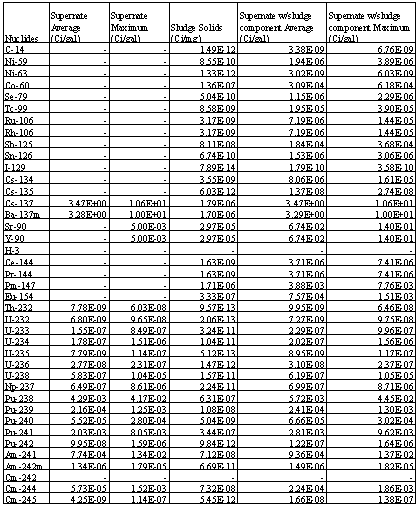
The average and maximum radionuclide concentrations in Table 2 are provided in Table 3. The sludge component nuclide distribution is also shown in Table 3 with the final combined supernate-sludge feed stream shown in the last two columns on the right.
Table 3. Radionuclide Concentration in SWPF Pilot Facility Feed
Notes:
Chemical Characterization
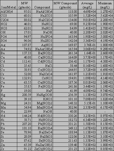
Table 4 shows the characterization of each waste tank supernate as extracted from WCS. The range of chemical and metal concentrations is shown in Table 5. The data from WCS shows ionic species and metal. Table 6 shows assumed compounds species and resulting concentrations. The values in Table 6 are derived by the ratio of compound molecular weight to initial characterization. The original nitrate ion concentration is equal to the stoichiometric sum of all the nitrate containing species. The arithmetic average and maximum concentrations listed in these tables are determined to each species. As such, the average and maximum do not represent an actual solution in the tank farms. As such, the solution ion charges are not balanced. In order to create a balanced solution as compounds, the hydroxide ion is adjusted, up or down, to balance the charge in the solution and total sodium concentration remains unchanged.
Table 4. Chemical Characterization of Waste Tank Supernates for SWPF Pilot Facility Feed (mg/L)
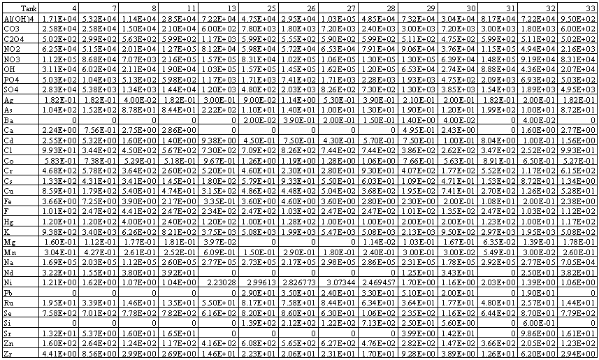
Table 4. Chemical Characterization of Waste Tank Supernates for SWPF Pilot Facility Feed (mg/L) (continued)
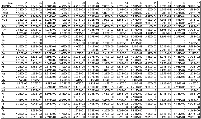
Table 5. Chemical Characterization of SWPF Pilot Facility Feed (mg/L)
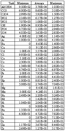
Table 6. Chemical Characterization by Chemical Species of SWPF Pilot Facility Feed
References