WSRC-TR-2000-00372
Plutonium Loading Onto Reillex HPQ
Anion Exchange Resin
E. A. Kyser
Westinghouse Savannah River Company
Aiken, SC 29808
This document was prepared in conjunction with work accomplished
under Contract No. DE-AC09-96SR18500 with the U.S. Department of Energy.
DISCLAIMER
This report was prepared as an account of work
sponsored by an agency of the United States Government. Neither the United States
Government nor any agency thereof, nor any of their employees, makes any warranty,
express or implied, or assumes any legal liability or responsibility for the
accuracy, completeness, or usefulness of any information, apparatus, product
or process disclosed, or represents that its use would not infringe privately
owned rights. Reference herein to any specific commercial product, process or
service by trade name, trademark, manufacturer, or otherwise does not necessarily
constitute or imply its endorsement, recommendation, or favoring by the United
States Government or any agency thereof. The views and opinions of authors expressed
herein do not necessarily state or reflect those of the United States Government
or any agency thereof.
This report has been reproduced directly from
the best available copy.
Available for sale to the public, in paper, from:
U.S. Department of Commerce, National Technical Information Service, 5285
Port Royal Road, Springfield, VA 22161, phone: (800) 553-6847, fax:
(703) 605-6900, email: orders@ntis.fedworld.gov online
ordering: http://www.ntis.gov/support/ordering.htm
Available electronically at http://www.osti.gov/bridge/
Available for a processing fee to U.S. Department
of Energy and its contractors, in paper, from: U.S. Department of Energy, Office
of Scientific and Technical Information, P.O. Box 62, Oak Ridge, TN 37831-0062,
phone: (865 ) 576-8401, fax: (865) 576-5728, email: reports@adonis.osti.gov
Summary
The proposed resin for HB-Line Phase II, Reillexä
HPQ, was tested in the laboratory under expected plant conditions and
was found to load a maximum of 117 grams of plutonium per liter of resin. With
a plutonium feed concentration of no more than 5 grams per liter, the 20-liter
resin column in HB-Line should not be capable of retaining more than 2.4 kilograms
of plutonium at any time during its life cycle. A batch size of 1 kilogram of
plutonium should be within the operating range of the process with minimal raffinate
losses as long as a full 20-liter charge of resin is loaded into the column.
Background
The new HB-Line facility was designed
and built in the early to mid 1980’s. Phase II of HB-Line is currently being
prepared for startup to stabilize Pu solutions. This facility was designed to
receive Pu (or Np) nitrate solutions from H-Canyon and convert them into oxides
for storage or shipment. After receipt of Pu solution, anion exchange columns
will both purify and concentrate the Pu nitrate solution, after which it will
be converted to an oxide via oxalate precipitation, filtration and calcination.
The existing tanks and interconnecting piping associated with anion exchange
are shown in Figure 1.
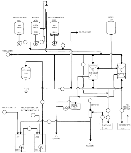
Figure 1. Process Flow Diagram of Anion Exchange Process in HB-Line
Pu solution will be received from H-Canyon
as a dilute Pu nitrate solution (2-3 g Pu/L, 3-5 M HNO3). Valence
and acid concentration adjustment will be performed in a feed adjustment tank
via the addition of ferrous sulfamate (FS), sodium nitrite and 64% HNO3.
In the past, Pu valence adjustment was performed by adding sufficient FS to
make the solution 0.05 M FS and then oxidizing the Fe2+ and Pu3+
to Fe3+ and Pu4+ via the addition of sodium nitrite.
The FS reduces all Pu 4+,5+,6+ to Pu 3+ and the nitrite
re-oxidizes the Pu3+ back to Pu 4+. Pu 4+
is the only oxidation state of Pu that forms the anionic nitrate complex that
loads onto anion resin. The high nitrate concentration and radiolysis will
produce sufficient HNO2 to oxidize both the Fe2+ and
Pu3+ after several days, but the nitrite addition allows the material
to be processed rapidly. A "heat-kill" has been used, instead of
a nitrite treatment, to accelerate the natural re-oxidation of Fe2+
and Pu3+ to a period of less than one hour. The valence adjustment
may be performed either before or after the acid adjustment, but it is preferable
to valence adjust first since the acid adjustment normally doubles the solution
volume and thus requires almost twice the quantity of FS to be used. This
affects the amount of Fe and sulfate in the waste stream. Once properly adjusted,
weapons grade Pu should remain stable as Pu4+ for weeks to months
due to the effect of nitrate complexation.
The anion column will be prepared for
a Pu run by "reconditioning" the resin bed with a quantity of 8
M HNO3 passed through the piping and the bed to flush dilute acid
from the system. HB-Line will pump the adjusted feed from the receipt/feed
adjustment tanks to a column feed tank. The feed solution will be pumped "up-flow"
through the column, absorbing the anionic Pu(NO3)62-
complex as it passes through the resin bed. The column raffinate (which contains
the cationic metal impurities and is normally waste) will pass by a NaI detector
along its path to an H-Canyon tank. This detector should indicate unexpectedly
large Pu losses during loading or decontamination. After a full batch of Pu
feed solution has been loaded onto the column (probably using one-half to
two-thirds of the resin bed’s physical capacity), the bed will be washed with
8 M HNO3 to remove residual impure solution from the equipment
and decontaminate the Pu loaded on the resin. This step will also be performed
"up-flow". The Pu will then be eluted with 0.35 M HNO3
by gravity feed from a head tank "down-flow" through the column.
The elution stream passes through a sight-glass that is instrumented with
fiber optics to a colorimeter to determine the point to start collecting Pu
into the product concentrate tank. The initial effluent from the column collected
during elution is commonly referred to as the "heads cut". The high
Pu concentration solution collected next is referred to as the "hearts"
or product cut. Any dilute acid concentration, dilute Pu concentration solution
collected near the end of the elution is referred to as the "tails"
cut. HB-Line is not planning on collecting a tails cut on a routine basis.
At the end of a column run, the column is left in a dilute acid concentration
state with little or no Pu heel. This is considered to be a safe condition
for storage until the next run. A NaI detector will monitor the Pu inventory
on the column throughout the column run to ensure that excessive Pu inventory
is not unintentionally loaded on the column.
Normally an anion exchange column would
only be partially loaded, leaving a large amount of excess capacity. This excess
capacity results in minimal losses to the raffinate stream. The capacity of
the resin must be known under normal process conditions to determine the batch
size. If loading is continued, the concentration of Pu in the raffinate stream
will gradually rise until visual "break-through" occurs. After visual
break-through, the resin continues to load Pu, but an ever-increasing fraction
of the Pu in the feed solution is not absorbed. Ultimately the Pu concentration
in the raffinate will reach the concentration in the feed and the resin bed
will absorb no additional Pu.
The anion exchange resin proposed for use
in HB-Line is Reillexä HPQ. Fred Marsh of Los
Alamos National Lab (LANL) and Reilly Industries jointly developed this resin
based on another polypyridine-based resin, Permutitt SK, which was used in Pu
processes in the late 1950’s. Better resistance to radiolytic and chemical damage
is attributed to these resins due to the use of the pyridine ring "N"
functional group. Marsh also found this resin to be attractive due to its relatively
high loading for Pu and its excellent elution behavior (2). In the 1996-7 timeframe,
Reilly Industries modified its manufacturing process to increase the anion exchange
sites yield by ~20%. This change cast some doubt on the applicability of past
data on the original version of this resin for future work with newly manufactured
batches of resin. The current work examined the Pu loading characteristics of
the "improved" resin. The first objective of this work was to measure
the resin capacity under HB-Line process conditions to determine the point at
which visual Pu break-through would occur. A second objective was to determine
the ultimate capacity of the resin column if loading continued well past the
point of visual break-through.
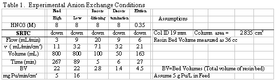
Process Flowrate Scaling
Plant scale anion exchange equipment is
typically 100 to 1000 times as large as that used in the laboratory. Normally
the process is scaled based on the linear velocity (Q/A, mL/min/cm2 º
cm/min) through the resin bed (which is related to residence time in
the bed) and the loading profile of the resin. If a laboratory column contains
resin at the same depth as the plant equipment, then the scaling problem is
primarily reduced to one of linear velocity. However, higher Pu concentrations
in the feed solution will produce a higher Pu resin loading. For these experiments,
a resin volume of 36 cm3 of settled resin was used in a 19 mm ID
glass column, resulting in a cross sectional area of 2.835 cm2. To
determine a conservatively high value for the Pu loading, a high-end concentration
value of roughly 5 g Pu/L feed was used in all runs. The targeted flowrate of
9 mL/min @ 5 g Pu/L for a 2.835 cm2 laboratory column was based on
a cross-sectional area for the HB-Line. The slower flowrate of 3 mL/min @ 5
g Pu/L (for the lab column) corresponds to a lower Pu loading rate (0.005 g
Pu/min/cm2) and the flow velocity is one-third of the baseline condition.
This rate serves to test for any significant increase in resin loading, caused
by a slow loading flowrate. Table 1 shows the current SRTC test conditions.
Experimental Column Operation
Resin Pretreatment
Three different resin pre-treatment methods
were used: 1) convert to nitrate form, 2) convert to nitrate form then irradiate,
and 3) convert to nitrate form then digest to remove low temperature exotherm.
All resin that was tested came from the same original manufacturer’s lot (#80302MA).
All resin was initially converted from the chloride form (as-shipped) to the
nitrate form by washing with 1 M NaNO3 (10 bed volumes (BV) in a
column was the preferred method, but other methods were acceptable). A large
sample of nitrate form resin was irradiated for 100 hr in a 60Co
irradiation source with a field of 1x10⁶ rad/hr for a total dose
of 1x10⁸ rad in July 1998 for this work and several related studies(1).
The third sample tested was treated by exposure to hot HNO3 (8 M,
85°C, 45 min) in a laboratory oven. NOx
fumes were evolved from the sample, but after the treatment, the low temperature
exotherm was no longer detectable by RSSTä testing
(1).
Column Loading
A sufficient quantity of resin must be converted
into the nitrate form and pretreated, if required, prior to loading the column.
The resin is generally loaded either by pouring dry resin beads into the column
and then wetted with water or dilute nitric acid or by slurrying the resin into
the column with water. The resin bed is settled by running water/dilute nitric
acid downflow through the resin bed to fill the excess void spaces until all
apparent gaps are filled. The final resin bed volume is adjusted by adding a
small amount of resin or removing excess resin with a slurry pipette. Once the
resin is loaded and settled into the column, every effort is made to not allow
the liquid head above the resin to drain below the top of the resin bed. Air
bubbles trapped within the moist bed are often very difficult to remove and
will cause channeling of the flow through the bed.
Feedstock Preparation and Valence Adjustment
Pu solution is prepared by adjusting the [HNO3]
to 7.5 to 8.5 M and performing a valence adjustment with ferrous sulfamate (FS).
Normally a valence adjustment is performed by adding sufficient FS to make the
solution 0.05 M FS and then followed by a "heat kill" to oxidize the
Fe2+ to Fe3+. The FS reduces all Pu 4+,5+,6+
to Pu 3+ whereas the heat kill re-oxidizes the Pu3+ back
to Pu 4+. The heat kill must be performed after the HNO3
has been adjusted to 8 M and consists of gently heating the feed solution to
50° C for 30 minutes. The high nitrate concentration
and heat produces sufficient HNO2 to oxidize both the Fe2+
and Pu3+. In 8 M HNO3 at 50°
C the half life for Fe2+ is on the order of 10 minutes compared
with 1 hr at 35° C and 10 hr at 25°
C. (9). The valence adjustment was performed either before or after the acid
adjustment; it is better done first because the acid adjustment normally doubles
the solution volume and thus requires twice the quantity of FS. The plant plans
to perform a nitrite addition to "kill-off" the FS. This approach
has historically been an alternative approach to the heat kill for restoring
Pu3+ solution to Pu4+ in both F-Area and H-Area and should
be equally effective. However, this method results in higher [SO42-]
in the feed and may increase the raffinate losses due to sulfate complexation
with Pu4+.
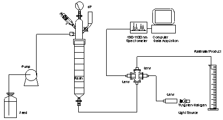
Lab Equipment
The column used in this work is shown in Figure
2. This column utilized #7 teflonÔ bushings
for connecting ¼ inch polypropylene tubing to the column. The column consists
of a 19 mm ID glass body to retain the resin bed and a headpiece. The headpiece
attached to the column body with a RodavissÔ
joint to allow the column to retain a larger pressure head than that allowed
by a ground glass joint. As a safety precaution, the head also had a Ace glass
pressure relief valve and a pressure gauge to monitor the pressure in case the
frit at the bottom of the column plugged. An additional arm with a stopcock
and funnel allowed the column to be vented. A sketch of the experimental setup
is shown as Figure 3. A standard FMI piston pump was used to pump feed, wash,
or elution acid through the column. A ½ inch SwaglockÔ
cross and ½ inch optic lens was used to fabricate a flowcell with a 2.54 cm
pathlength. A pair of fiber optic lines previously installed through the ceiling
of the glovebox allowed a light signal to be brought into the glovebox, passed
through the flowcell and carried out to a Zeiss spectrometer controlled by NT-based
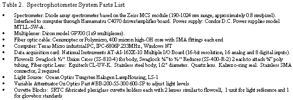
computer. A detailed parts list for the complete spectrophotometer system used
is given in Table 2.
Pu Loading
Sufficient Pu feedstock was prepared for one
or more break-through column runs. A sample was taken and analyzed for total
acid/free acid, total alpha by radscreen and gamma scan. Because of the importance
of the Pu concentration feed values, the radscreen and gamma scans for the feed
were normally performed in triplicate. At the beginning of the column run, several
column volumes of 8 M HNO3 were fed to the column to displace the
dilute acid the resin was stored in from the previous run. At this point in
time the spectrophotometer was checked for proper operation and a new "zero"
spectrum was stored (background with no Pu in the flow cell). The Pu feed was
then pumped downflow through the column at approximately the desired flowrate,
with the raffinate passing through the flow cell and being collected and measured
in one of several graduated cylinders. The amount of Pu in the raffinate was
monitored by both visual inspection and by periodic spectra taken by the instrumentation.
"Grab" samples of the raffinate were also taken on a periodic basis
during the course of the loading step and analyzed for Pu content by alpha and
gamma counting. The spectra taken were stored along with the time and volume
of raffinate collected and the Pu concentrations predicted by the model(s) were
matched up to the amount of Pu that had been loaded onto the column. The feed
flowrate was periodically checked with a 10mL graduated cylinder and a stopwatch.
The flowrates were somewhat variable (sometimes ±
50% of the targeted value), but the average flowrate could generally be regulated
within 15% of the desired value. The Pu loaded onto the resin was also visually
monitored. Flow abnormalities within the resin bed sometimes caused visible
"tailing" of the loaded Pu (e.g. Pu loaded non-uniformly on the resin
where the Pu interface is further down the resin bed on one side of the column
than the other). As the Pu interface (observed as a green boundary) approached
the bottom of the resin bed the levels of Pu in the raffinate rose gradually
(to ~0.1 g Pu/L) and the frequency of spectra measurements was increased. Pu
"break-through" could be visually detected in the raffinate solution
in the range of 0.5 to 1 g Pu/L. For a period of time before and after visual
break-through, the Pu concentration in the raffinate rapidly rises from <0.1
to ~2 g Pu/L. As loading continues, the concentration continues to rise, but
more slowly as it asymptotically approaches that of the feed concentration.
During this time, a significant fraction of the Pu in the feed solution continues
to load onto the resin as Pu diffuses deeper into the resin bed and the resin
becomes saturated with Pu. The raffinate was collected in two cuts. The first
was collected up to the point that visual break-through was detected and the
second was collected from that point past the end of the loading phase and through
the decontamination wash. This method of collection allowed the early raffinate
to be discarded, while recycling the raffinate after break-through.
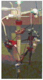
Figure 2. Pu Column Used in Experiments
Figure 3. Experimental Setup
Pu Washing and Elution
When the concentration in the raffinate was
approximately 90% of that in the feed (or when the prepared feedstock was exhausted),
the loading was stopped. Allowances then had to be made to displace the residual
Pu feed solution from the resin bed and feed line. There was unloaded Pu in
the system due to void space in the column (~50 volume percent or 18 mL), the
head-liquid volume above the resin (10 to 40 mL) and finally the liquid volume
still in the feed-line (<10mL). Normally this was eliminated by pumping the
feed line dry and allowing the head liquid to drain (without letting the level
drop below the top of the resin) to a minimal volume above the resin bed (0
to 5 mL). A short decontamination wash of the resin column with 50 mL of 8 M
HNO3 was then performed to remove most of the FS residue and displace
the residual Pu feed solution. This wash was included with the second raffinate
cut for material balance purposes and futur e recovery of the Pu. The column
was then completely eluted with 200 to 400 mL of 0.35 M HNO3 at 6
mL/min downflow. Although the spectrophotometer was not calibrated for Pu in
dilute acid, it still proved useful in detecting trace Pu in the effluent during
the latter stages of elution. Because several runs were made with each sample
of resin loaded into the column, it was essential that all of the Pu be eluted
from the column prior to the next run. After the visible Pu had been removed
from the resin, the run could then be safely interrupted and the remainder of
the elution could be continued the next day.
Analytical
Samples were taken of feed solutions and composite
raffinate and product solutions, as well as "grab" samples of the
raffinate stream. These samples were routinely analyzed by radscreen and gamma
scan analyses to determine the total alpha activity and the 241Am
activity to obtain a value for the Pu alpha activity. A specific activity of
1.58x10¹¹ dpm/g Pu was used to convert Pu alpha activity to Pu mass.
This conversion factor (specific activity) was known from the history of the
Pu used in this work. Radscreen values were corrected from the default 90% efficiency
of the method to a 97% efficiency that is specific to Pu/Am materials to give
a more accurate result.
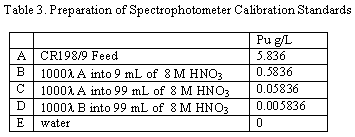
Calibration of Spectrophotometer
The spectrophotometer was calibrated for this
work by measuring spectra of the feed solution prepared for runs CR198/9 (analyzed
for Pu concentration) as well as the spectra of volumetric dilutions of that
known Pu solution with 8 M HNO3 (see Table 3). The Pu for the dilutions
was pipeted into a weighed volume of 8 M HNO3 that would give the
correct dilution volume based on a density of 1.25 g solution/cm3.
The spectra of four samples and deionized (DI) water were measured in duplicate
from 191 to 1024 nm in November 1998 in 1-cm plastic cuvettes. The same equipment
was used for all column runs described in this report.
These spectra were mathematically processed using the SRTC-ADS
developed SRLMVA program. A PLS (partial least squares) model was built on duplicate
spectra from standards A through E (Table 3). Second derivative preprocessing
was performed on each spectrum and the modeled wavelength range was limited
to 450 to 850 nm to avoid noise and interferences. Calibration sample spectra
are shown in Figures 4 and 5. Several development versions of the SRTC-ADS ZMMIS
program were used over the course of this work to acquire data from and control
the multiplexer and spectrometer. This program displayed the spectra in near
real time and used the PLS model (from SRLMVA) to calculate a Pu concentration
during the column run. The spectra taken during the column run were saved for
future data analysis.
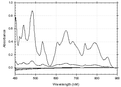
Figure 4. Raw Pu Spectra Used to Develop Model
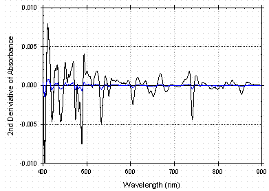
Figure 5. 2nd Derivative of Pu Spectgra Used to Develop Model
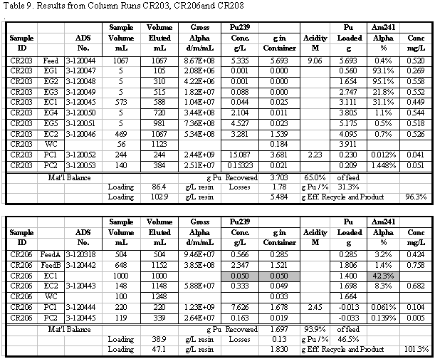
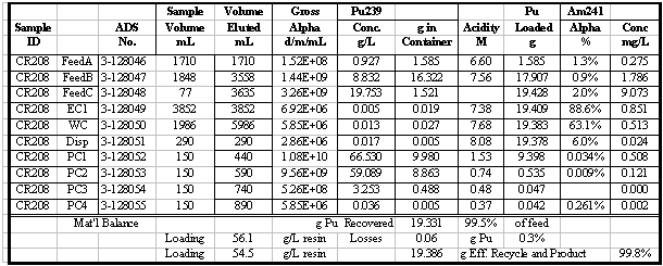
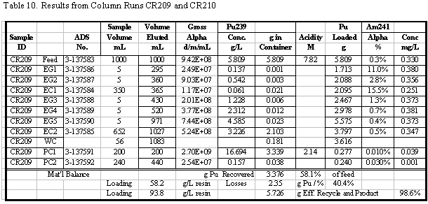
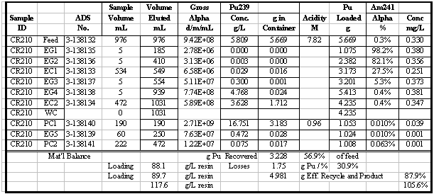
Results and Discussion
A series of column runs was performed with
the current version of Reillexä HPQ. For each
experiment, composite samples of the feed, raffinate, and product solutions
were analyzed (along with selected "grab" samples) and submitted for
analysis. The results from those analyses and the volume of each solution were
used to calculate a material balance for each experiment. The amount of Pu absorbed
onto the resin was calculated as the difference between the cumulative amount
fed and the amount found in the raffinate solutions. This method was used to
calculate the visual break-through loading of the resin. The saturated loading
was also calculated in this same fashion and was checked by measuring the total
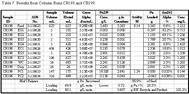
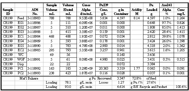
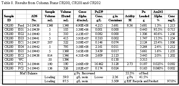
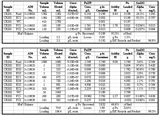
amount of Pu found in the eluate (product) solutions. A sample set of results
for one of the column runs and some sample calculations for that run are shown
in Table 4. Additional results for the other runs are given in the appendix.
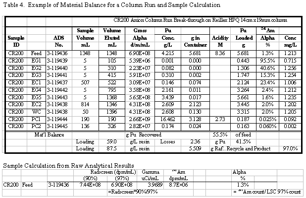
Table 5 summarizes the Pu loading results for
the 12 column runs that used the 1998 lot of Reillexä
HPQ. Some of these runs were made to recover Pu and did not involve loading
to Pu break-through. Flowrates and feed concentrations varied somewhat and are
also shown in Table 5. Visual break-through occurs in the range of 59 to 88
g Pu/L resin. The determination of visual break-through is somewhat subjective
making it difficult to determine if experimental changes gave a significantly
different loading. The results of these tests indicate that there could be a
15 to 30% increase in loading caused by lowering the flowrate from 3 down to
1 mL/min/cm2. Some increase is expected, but this shows it to be
at most a relatively modest effect. The effects of the various pretreatment
methods on visual break-through are less clear. No large change is loading was
observed by any of the pretreatment methods. Marsh (3) claimed to observe increases
in resin capacity by a boiling acid treatment due to an increase in surface
area. The acid treatment in this study was much less severe on the resin structure
than the one performed by Marsh. Crooks (1) observed a significant breakdown
in resin structure after boiling resin in concentrated HNO3, but
a sample of this "boiled" resin was not tested for Pu loading because
the breakdown of the resin was expected to result in an unacceptable pressure
drop across a column. Marsh (4) also observed that alpha irradiation did not
greatly reduce the Pu capacity. The results of the current work show a small
increase in capacity (on the order of 15%), but this result is probably not
statistically significant.
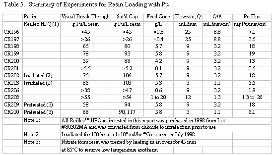
A number of these runs were continued well
past the point of visual break-through and approached the point of saturating
the resin with Pu. Saturated Pu loading in the range of 80 to 117 g Pu/L resin
was calculated (based on the amount of Pu eluted). Typically 20 to 30% more
Pu was loaded after visual break-through was detected. In several instances
50 to 60% more was loaded, but those runs had relatively low values for break-through
loading. The run with the highest loading, CR210, had a material balance discrepancy
probably due to a significant error in an analytical result. Two results are
reported for that run: 90 and 117 g Pu/L, the first calculated directly and
the second calculated from the material balance. Based on all the data from
that run, it is more likely that 117 g Pu/L is the correct result, but that
value is calculated differently than for all the other runs.
Up to this point all results that have been
discussed are based on analytical measurement of "composite" samples
from the column runs. The spectrophotometer system provided direct on-line measurements
of the Pu concentration in the effluent during the column loading. Utilizing
the individual spectra time stamp, the Pu concentrations predicted by those
spectra (from the saved spectra), and the experimental records, the Pu concentration
in the raffinate was reconstructed as a function of loading time and feed volume.
Figure 6 shows a plot of the Pu concentration in the raffinate for several column
runs. There are some gaps in the data, but the data generally show that the
column initially loads nearly all the Pu from the feed, leaving a very low Pu
concentration in the raffinate. Eventually a point is reached where the Pu concentration
rapidly rises to 30 to 40% of the feed concentration. Loading continues beyond
that point, but an increasing fraction of the Pu in the feed does not get absorbed
by the resin bed and passes through the column in the raffinate.
Figure 7 shows the cumulative amount of
Pu both loaded on the column and collected in the raffinate bottle during the
course of the same column run. The upper family of curves represents the Pu
loaded on the resin, while the lower family of curves represents the Pu that
passed through the column as part of the raffinate and was collected in the
effluent bottle as a waste or recycle stream. As can be seen by looking at the
right hand axis, 50 g Pu/L resin can be loaded with minimal losses, but in the
range of 80 g Pu/L resin Pu losses started to become significant in many of
the runs. The resin loading values that can be determined from Figures 6 and
7 are measured independently from the values shown in Table 5 because they come
from the spectrophotometric measurements rather than from sample analysis. The
general agreement is fairly good. The slow change in the concentration profiles
shown in Figure 6 support a maximum loading of up to ~120 g Pu/L for the current
batch of Reillexä HPQ.
All runs made in this laboratory were performed
with downflow loading, where the hydraulic pressure tends to compress the resin
bed. The actual plant column will be loaded up-flow. If the column is not full
of resin and the resin bed is not compressed by the column "top-hat",
the resin beads may fluidize and the efficiency of mass transfer may be reduced.
This situation should not occur as long as the resin bed fills the column body.
Future laboratory work on elution will use a column design that will allow up-flow
loading and any additional complications may be recognized at that time.
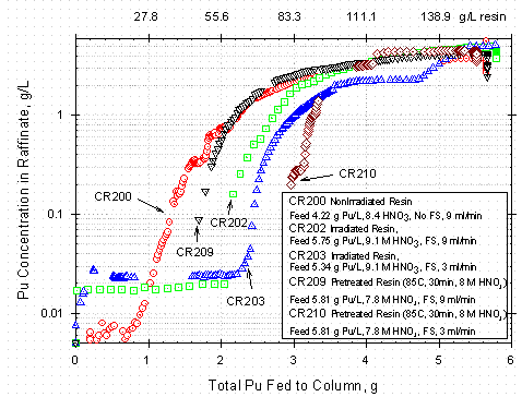
Figure 6. Pu Concentration in Raffinate during Break-through for Various
Conditions and
Resin Pre-Treatment as a Function of Total Pu Fed to Column
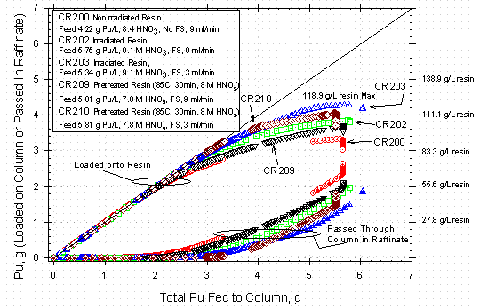
Figure 7. Pu Loading for Reillex HPQ for Various Conditions and Resin Pre-Treatments
as a Function of Cumulative Pu Fed to Column
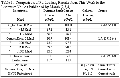
Comparison with Literature Results
Marsh performed the initial Pu work with Reillexä
HPQ. Published reports documented the effects of radiation exposure on the version
of the resin that was produced in the late 1980s (2,3,4). Although the current
work uses a version of the resin with an increased capacity and uses different
experimental techniques, some comparison of the data is possible. Marsh performed
dynamic batch contact tests in which the amount of Pu loaded onto resin samples
exposed to ~5 g Pu/L, 7 M HNO3 solution was measured over time. After
converting the batch contact into units of g Pu/L resin, a rough comparison
can be made between the current data and the literature results. The Marsh’s
15-minute batch contact data (2,3,4) has comparable time for mass transfer to
that of the 12-minute residence time (H/(Q/A)) of most of the column runs in
this work. Marsh’s 6-hour contact data (2,3,4) reflect values that approach
equilibrium values. Table 6 tabulates a comparison of Marsh’s data with the
current work. The improved capacity resin appears to have an ~10 % increase
in Pu loading capacity. Interestingly, Marsh showed a small decrease in Pu capacity
as the resin was irradiated with either gamma or alpha dose, but the current
work appears to show a small increase. It should be noted that while Marsh found
a relatively good radiation stability of Reillexä
HPQ compared to the various polystyrene based resins, the resin capacity steadily
dropped above 100 Mrad dose. These results suggest that any effort to extend
the useful life of Reillexä HPQ much beyond
the current limit of 100 Mrad would have limited value.
Uncertainties
As previously stated, instantaneous flowrates
occasionally varied widely form the targeted value, but adjustments were quickly
made to keep the average flowrate within ~15 % of the targeted value. Since
resin loading was found to be only a weak function of flow rate the flowrate
uncertainty probably contributes < 1% to the uncertainty in the loading results.
Under the conditions that most column runs
were made (9 mL/min, ~5 g Pu/L), ~0.05 g of Pu was fed during each minute of
the loading cycle. During the loading time prior to break-through, enough Pu
was loaded to increase the resin loading by ~1.4 g Pu/L. Thus the subjective
nature of visual break-through detection may make a contribution to the resin
loading uncertainty of up to 3 g Pu/L.
Measuring the resin bed depth to determine
the volume of resin in the column is relatively accurate measurement, but the
resin beds pack into the bed unevenly and settle during the initial use. This
uncertainty is estimated at ~2% based on observations of settling as the resin
columns are loaded. However additional resin was added during column setup to
keep the resin volume at its targeted value. This adjustment should bias the
amount of resin loaded towards a higher value and likewise bias the resin loading
values upward over what would be observed if such care were not taken. Since
several runs were made with the same resin column, this uncertainty does not
contribute to the variation in reproducibility between successive runs that
use the same resin column.
Analytical measurement uncertainty is generally
dominated by dilution errors. Typically, dilution error is estimated as ~3%
for this work due to the equipment. Operator errors could easily cause a 30%
or more error on an individual sample, but those errors would normally be recognized
due to inconsistency and rechecked. An probable error of this type on a CR210
product solution was not recognized until later and was not resolved. The feed
solutions were routinely analyzed in triplicate to eliminate these errors because
the feed solution concentration has a dominant effect on the loading results.
A material balance was calculated for each
run by taking the solution volumes and the analytical results from the feed,
product and waste streams. Most column runs had an overall material balance
uncertainty of < 4% (many had < 2% uncertainty). Due to a probable dilution
error in the analysis of a product sample, Run CR210 could not be resolved better
than a +6 to -13% uncertainty (depending what which way the calculation was
performed). These results support the viewpoint that routine analytical results
have a precision of ~4 %.
The spectrometer itself is a very precise
measurement instrument, but accuracy of its results depends on the preparation
of the calibration solutions and the modeling of the spectra from those solutions
to produce a predictive model. In this case, the standards were prepared by
volumetric dilution and thus dilution errors contributed 1 to 2 % to the uncertainty
of the resulting model. Because the concentration of the initial solution was
based on analytical measurements, the total uncertainty in the concentration
of the standards was in the range of 3 to 6%. The uncertainty in the predictive
model is difficult to quantify, but is assumed to be considerable less than
the uncertainty in the concentration of the standards in this case. Because
the more useful measurements were made in the upper end of the concentration
range where less dilution error was involved, measurement of column break-through
is probably in the low end of this uncertainty range. More accurate calibration
standards could have been prepared by gravimetric means, but that effort was
not judged to be worthwhile for this particular application. These measurements
provide support for the loading results and are included to provide a better
understanding of how break-through progresses.
Conclusions
Based on a ~5 g Pu/L feedstock in ~8 M HNO3,
HB-Line can expect to load from 80 g Pu/L up to a maximum of 117 g Pu/L onto
Reillexä HPQ anion exchange resin if the columns
are run without regard to raffinate losses. If the columns are operated for
reasonable loss levels, the resin should load 59 to 88 g Pu/L without significant
break-through. This result means that a column containing 20 L of resin may
hold 1.2 to 1.8 kg of Pu under nominal conditions, but might hold 2.4 kg of
Pu under extreme conditions. These conclusions should hold for resin exposed
to a radiation dose of up to 1x10⁸ rad or for resin treated to remove
the low-temperature exotherm.
References
- W. J. Crooks, E. A. Kyser, S. R. Walters, "Qualification
of Reillexä HPQ Anion Exchange Resin for Use
in SRS Processes," WSRC-TR-99-00317, Westinghouse Savannah River Company,
Aiken, SC (March 10, 2000).
- S. F. Marsh, "Evaluation of a New Macroporous Polyvinylpyridine
Resin for Processing Plutonium Using Nitrate Anion Exchange," LA-11490,
Los Alamos National Laboratory, Los Alamos, NM (April 1989)
- S. F. Marsh, "The Effects of In Situ Alpha-Particle Irradiations
on Six Strong Base Anion Exchange Resins," LA-12055, Los Alamos National
Laboratory, Los Alamos, NM (April, 1991)
- S. F. Marsh, "The Effects of Ionizing Radiation on Reillexä
HPQ, A New Macroporous Polyvinylpyridine Resin and on Four Conventional Polystyrene
Anion Exchange Resins," LA-11912, Los Alamos National Laboratory, Los
Alamos, NM (Nov, 1990)
- M. L. Hyder, W. C. Perkins, M. C. Thompson, G. A. Burney,
E. R. Russell, H. P. Holcomb, and L. F. Landon, "Processing of Irradiated
Enriched Uranium Fuels at the Savannah River Plant," DP-1500, E. I. Du
Pont de Nemours & Co, Savannah River Laboratory, Aiken, SC, (April, 1979)
Appendix