WSRC-TR-2000-00350, Revision 0
CST Particle Size Reduction Tests
R. C. Odom and F. G. Smith, III
Westinghouse Savannah River Company
Aiken, SC 29808
This report was prepared as an account of work sponsored by an agency of the United States Government. Neither the United States Government nor any agency thereof, nor any of their employees, makes any warranty, express or implied, or assumes any legal liability or responsibility for the accuracy, completeness, or usefulness of any information, apparatus, product or process disclosed, or represents that its use would not infringe privately owned rights. Reference herein to any specific commercial product, process or service by trade name, trademark, manufacturer, or otherwise does not necessarily constitute or imply its endorsement, recommendation, or favoring by the United States Government or any agency thereof. The views and opinions of authors expressed herein do not necessarily state or reflect those of the United States Government or any agency thereof.
This report has been reproduced directly from the best available copy.
Available for sale to the public, in paper, from: U.S. Department of Commerce, National Technical Information Service, 5285 Port Royal Road, Springfield, VA 22161, phone: (800) 553-6847, fax: (703) 605-6900, email: orders@ntis.fedworld.gov online ordering: http://www.ntis.gov/support/ordering.htm
Available electronically at http://www.osti.gov/bridge/
Available for a processing fee to U.S. Department of Energy and its contractors, in paper, from: U.S. Department of Energy, Office of Scientific and Technical Information, P.O. Box 62, Oak Ridge, TN 37831-0062, phone: (865 ) 576-8401, fax: (865) 576-5728, email: reports@adonis.osti.gov
Introduction
Ion exchange using Crystalline Silicotitanate (CST) is one of the alternative processes being evaluated for removal of cesium from the aqueous fraction of high level waste currently in storage at the Savannah River Site (SRS). The proposed process using CST ion exchange would involve passing filtered salt waste solution through a fixed bed of CST that would adsorb the cesium. The spent resin, loaded with cesium and highly radioactive, would then be slurried from the column and ultimately blended with the sludge waste stream in the Defense Waste Processing Facility (DWPF) Sludge Receipt and Adjustment Tank (SRAT) for incorporation into a waste glass product.
Initial testing in a mock-up of the DWPF Hydragard sampling system with a melter feed of sludge simulant and frit containing 10 wt% as-received CST revealed that the Hydragard sampler rapidly plugged because of the large particle size (500 – 700 mm) of the as-received CST [1]. Figure 1 shows the particle size distribution of as-received CST. Subsequent Hydragard tests showed that a sludge/frit melter feed containing CST with a particle size less than 80 mesh could be sampled although there was evidence that the Hydragard samples were slightly lean in frit [1]. As a result of these tests, it was evident that the particle size of spent CST resin would have to be reduced before blending with the DWPF sludge stream. A Task and QA Plan was written and approved to address this and other issues on interfacing CST ion exchange with the DWPF flowsheet [2]. As a part of this plan, the Savannah River Technology Center (SRTC) was tasked with the responsibility to review methods of particle size reduction and to arrange for preliminary demonstrations of promising technologies that would potentially be applicable for CST loaded with cesium.
Based on a review of existing literature on particle size reduction and experience at other DOE sites [3], two vendors were selected to demonstrate methods of particle size reduction. CST size reduction tests were contracted to IKA Works, Inc. in Wilmington, North Carolina and Micro-Grinding Systems, Inc. in Little Rock, Arkansas. The work scope for these tests requested demonstrations of reducing the as-received CST to a maximum particle size of 177 microns (80 mesh) and a maximum particle size of 20 microns. The IKA machine reduces particle size by passing the slurry flow through a series of concentric gear teeth rotating at high speed with a small clearance from a stationary surface. Size reduction is controlled by the gear teeth spacing, rotation speed and slurry flow. The Micro-Grinding system reduces particle size by passing the flow through a vibrating bed of cylinders that impact the particles. Particle size is controlled by adjusting the slurry flow, slurry solids concentration and the grinding medium used. Thus, the two tests looked at markedly different techniques for particle size reduction. The CST used in all of the testing was IONSIVÒ IE-911 (UOP, LLC, Molecular Sieves Division, Des Planes, IL), Lot Number 2081000009.
Keywords: Salt Disposition, CST, Particle Size Reduction
SummaryBoth vendors demonstrated the capability of size reducing as-received CST to less than a maximum particle size of 177 microns. IKA did not demonstrate this during the intended test but the results of both tests clearly indicate that there is a combination of heads between coarse/coarse/coarse and superfine/superfine/superfine that would produce a maximum particle size 100% less than 177mm. CST is a relatively friable material that did not severely challenge the grinding capabilities of either device. However, neither vendor was entirely successful at reducing as-received CST to less than a maximum particle size of 20 microns. A summary of the test results is provided in the table below.
Summary of Vendor Test Results
|
Target Maximum Particle Size |
IKA Works |
Micro-Grinding |
||||||||||
|
Percent Meeting Target |
Grinder Setup |
Mean Size (mm) |
Percent Meeting Target |
Slurry Solids Wt% |
Mean Size (mm) |
|||||||
|
177 mm |
89 % |
3 Coarse rotors |
81 |
100 % |
16.5 |
20 |
||||||
|
20 mm |
72 % (100% < 177 mm) |
3 Superfine rotors |
16 |
88 % |
26.1 |
9.4 |
||||||
Through a miscommunication with the vendor, IKA targeted mean (not maximum) particle diameters of 177 microns and 20 microns during their testing. Consequently, only 72% of the particles passed the 20 mm maximum size specification. This was achieved in a single pass through a Dispax ReactorÒ using 3 superfine rotors operating at 4320 rpm. This configuration did reduce the maximum particle size below 177 mm. Subsequent conversations with the vendor indicated that, to reduce the maximum CST particle size to 20 mm, would require either multiple passes through the reactor or possibly a different machine. The IKA testing was accomplished using an approximately 10 wt% slurry of CST in water.
Micro-Grinding Systems successfully size reduced 100% of the CST to a maximum particle size of 177 microns and approximately 88% of the CST to a maximum particle size of 20 microns. The test mill used at Micro-Grinding consisted of a vibrating steel cylinder approximately 2 feet long and one-half foot in diameter about half full of iron rods. The Micro-Grinding mill was operated with a CST-water slurry having greater than 10 wt% solids.
A key observation during IKA testing was that it was necessary to establish water flow through the reactor before introducing the CST to avoid system pluggage. Initial testing with a 10 wt% CST-water slurry fed directly from a mixing vessel into the reactor’s inlet piping resulted in complete pluggage of the inlet pipe. This was attributed to the extremely rapid settling characteristics of the as-received CST. During the Micro-Grinding tests, dry CST and water were simultaneously fed to the mill without encountering any pluggage problems.
During scoping runs with the IKA tests, some CST with an average particle size of around 3 mm was produced. It was observed that these solids settled out of suspension over a 48 hour period but were easily resuspended with minimal agitation.
IKA Grinding Test
On May 12, 2000, IKA Works representatives conducted several tests for reducing the particle size of CST using the Dispax Reactorâ (DR3-6 series) at their test facility in Wilmington, North Carolina. Prior to the testing, two 25 lb batches of dry as-received CST were shipped to IKA along with stainless steel drums in which the size-reduced CST-product slurries were collected and shipped back to SRS. The tests were performed by Mike Cordle and Scott Bitter of IKA Works and were observed by three representatives from the Savannah River Site. Elmo Amayo, a chemist with IKA, performed the particle size analyses. The SRS representatives at the test were Richard Odom (SRTC), Chi Leung (HLWE), and Ram Kesavan (HLWE).
The tests were conducted to accomplish the following objectives:
A CD-ROM describing the Dispax ReactorÒ was provided by Mike Cordle, Regional Sales Manager, Process Division of IKA. (Ram Kesavan has placed the CD on a server at SRS and a printed copy is provided in the Appendix).
IKA Test Procdure
A Dispax ReactorÒ was already in place in the lab and the first test was to try to achieve an average particle size of 20 micron. IKA personnel configured the reactor to their "best guess" for the CST and decided to use a 3-stage fine/fine/superfine head configuration. Enough water was charged to the feeding vessel to obtain a 10 wt.% solution using approximately three pounds of CST. After vigorous agitation of the water had been achieved, the CST was dumped into the vessel and the ball valve was immediately opened to allow the solution to flow into the reactor. The CST sank to the bottom of the vessel immediately and lodged in the pipe. No flow at all was observed. The piping was disassembled and revealed a mass of CST lodged in the pipe. IKA personnel were surprised by how rapidly the CST settled and clogged the pipe.
The CST was easily rinsed from the equipment. At this point, IKA decided to start the water flow in a loop from the outlet of the feed vessel through the Dispax with the outlet of the Dispax directed back into the top of the feed vessel. With this modification, water flow was initiated at 6 gpm with vigorous agitation in the feed vessel. The CST was then dumped into the feed vessel all at once. Flow immediately ceased and it became obvious that the CST would have to be slowly metered into the feed vessel. At this point, IKA decided to change heads to a medium/fine/superfine head configuration in an effort to present less of an obstruction to the CST as it entered the reactor head. They also installed a 30-gallon round bottom feed tank with a shorter pipe run to the Dispax. See photo below for illustration of successful setup.
After these modifications had been made, the same amount of water as was used in the first test was charged to the feed tank, vigorous agitation in the feed tank was initiated, the ball valve was opened and the reactor energized establishing a flow of about 6 gpm. The CST was introduced into the mixing tank at approximately one pound every 10 seconds. As soon as the CST began to be fed, the outlet pipe of the reactor was redirected so that another IKA operator could catch the resulting slurry in a bucket. After all of the CST (3 lbs.) had been fed to the tank (in about 30 seconds), and all of the slurry had been collected in a bucket, the unit was shut down and a sample collected for analysis.
The analysis revealed that the CST had been reduced from its original, average particle size of 479 microns to an average of about 50 microns. At this point it was agreed that a workable procedure had been developed and subsequent tests were conducted using the same procedure. Rotors and stators were changed until a combination was found that would yield a 20 micron particle size. It took three more tests to perfect the reactor configuration, but an average particle size of 20 microns was achieved using a head configuration of superfine/superfine/superfine. The motor speed was 4320 rpm at 73 Hz. At this point, the remainder of the 25 pounds of CST, as well as the first three batches were run through the Dispax ReactorÒ using the same procedure and Dispax configuration as previously used in the successful 20 micron run. All of this material was drummed into a stainless steel drum, agitated and sampled. The material was returned to SRS for confirmatory particle size measurements and for use in mixing studies.
The remaining task was to demonstrate the capability of the Dispax ReactorÒ to reduce the particle size of the as-received CST to an average particle size of 177 micron. After three scoping tests, an average CST particle size of 177 microns was obtained by using a coarse/coarse/coarse head configuration and a motor speed at 3600 rpm at 72 Hz. However, approximately nine pounds of CST were used to establish the correct combination of rotors and stators. Consequently, the CST-water slurry with an average CST particle size of 177 microns contained only about 16 lbs of CST. The CST used in the scoping tests was drummed separately and also returned to SRS. If needed, this slurry could be converted to one containing a maximum CST particle size of 20 microns.
Some of observations made during the testing included the fact that there was some settling of the solids after size reduction, even at the smallest particle sizes. In fact, IKA personnel fed a slurry containing CST at an average particle size of 22 micron (obtained during one of the scoping runs) back into the reactor for a second pass. An average CST particle size of 3 microns was obtained. There was evidence of settling of the CST from this slurry beginning after only a few minutes. However, there also appeared to be a significant amount of suspended solids in the slurry. Further evaluation by IKA personnel revealed that significant settling had occurred after allowing the slurry to settle over the weekend. However, they reported that only a minimal amount of stirring brought the solids back into suspension almost immediately.
It was apparent that IKA did not expect the as-received CST to fall out of suspension so rapidly. Consequently, IKA personnel were forced to be a bit more innovative at the outset of the trial runs than they had anticipated. As they familiarized themselves with the material, it was apparent that they could achieve any size reduction requested using the Dispax ReactorÒ . There is also some flexibility in attaining a specific size reduction in addition to selecting the rotor head configurations. For a given head configuration, the particle size can be varied by altering the motor speed. This capability may be of great use if, for a given head configuration, extended testing of the Dispax unit shows some deterioration in efficiency.
Some of the vital statistics of the Dispax ReactorÒ employed by IKA during these tests are:
According to IKA, when processing solutions at around the viscosity of water, the Dispax unit generates a head pressure of 30 psig. They strongly suggest the use of a booster pump, however, as they acknowledge the fact that the Dispax is not an efficient pump.
IKA Test Results
Figure 1 shows the particle size distribution of the as-received CST used in the size reduction tests. Figures 2 and 3 show the particle size distributions achieved by IKA in the 20 micron and 177 micron tests, respectively. These size distributions were confirmatory measurements made at SRTC by sampling the drums of size reduced material returned from the test. Figure 3 shows that as much as 4% of the CST was able to pass through the coarse gears without grinding and still has a particle size greater than 352 mm. For the 20 mm target grind, the results show a mean particle size of 16 mm with about 72% of the CST reduced to below 20 mm in size. For the 177 mm target grind, the results show a mean particle size of 81 mm with about 89% of the CST reduced to below 177 mm in size. As noted previously, IKA targeted an average particle size at what was intended to be a maximum size. However, the results show that a maximum particle size of less than 177 mm could be achieved by some intermediate combination of heads.
Micro-Grinding Test
Another test of CST particle size reduction was performed at Micro-Grinding Systems, Inc. in Little Rock, Arkansas on Friday June 16, 2000. Frank Smith (SRTC) together with Ram Kesavan and Chi Leung of HLWE witnessed the test. Micro-Grinding Systems designs and manufactures a VibroKinetic Energy (VKE) grinding mill that size reduces material by passing it through a vibrating cylinder partially filled with metal rods or some other grinding media. The mechanical impact of the grinding medium on the material as it flows through the cylinder produces the crushing or grinding action. Particle size is controlled by adjusting the residence time, solids concentration, and the configuration of grinding medium in the mill.
The Micro-Grinding mill was selected for use at the West Valley Site to size reduce zeolite particles in a water slurry. Hence the company has some experience with using their equipment in a remote radioactive environment. West Valley selected the Micro-Grinding mill over competing equipment, such as the IKA grinder, on the basis that it could readily grind a zeolite slurry contaminated with rust and sand. The equipment is of a relatively simple and robust design that makes it very suitable for this application. Since we do not anticipate that the CST slurry will be similarly contaminated with debris, some of the West Valley selection criteria may not apply to the SRS process. Nevertheless, it was felt that an evaluation of this equipment for CST size reduction was warranted.
Micro-Grinding Systems, Inc. is a small business with only five employees. It is not a manufacturing company but rather offers engineering services. That is, they hold the rights to the VKE grinding mill (patent pending) and will help design a process to use this technology for a particular size reduction application. They will design a mill suitable for the intended application and subcontract the manufacture. They were able to do this within the constraints of DOE procurement for West Valley. They have a local shop with welding certification that is able to build grinders to their specifications. The grinder is essentially a steel cylinder with a heavy-duty motor attached to the bottom and end plates with inlet and outlet ports. The cylinder is suspended by springs in a metal frame and partially filled with the grinding medium. The grinding medium can be full-length steel rods, as were used in the CST tests, short zirconia cylinders, steel balls or ceramic balls. This simple design readily allows custom manufacturing of mills sized for a required throughput. The test mill would require a lubrication line to the motor for extended operation. However, the company could also supply a motor with sealed bearings for radioactive service.
Micro-Grinding Test Procedure
Approximately 25 pounds of CST was ground to a particle size of less than 177 microns and another 25 pounds of CST was ground to a particle size of less than 20 microns during the tests. The 177 micron particle size was produced by feeding dry CST at 30 lb/hr and about four times that amount of water into the mill. Post test measurements showed that, on average, these feed conditions produced a slurry having 16.5 wt% solids. A quick evaluation of the size reduction was made by sieving the effluent from the mill through an 80 mesh screen and a more exact measurement made using a Malvern particle size analyzer. The smaller particles were produced by feeding 10 lb/hr dry CST with between one and two times the water into the mill (26.1 wt% solids on average). Less water in the mill and longer retention times increased the milling action. Screening could not be used to estimate the grinding efficiency for the smaller particle size and machine setup relied on the Malvern particle size determinations. The 20 micron grinding could possibly be done more efficiently using short zirconia cylinders as the grinding medium. Both size-reduced CST fractions were returned to SRTC for additional characterization and for use in slurry mixing tests.
A picture of the Model 624 Laboratory Mill used in the CST grinding tests is shown in Figure 4. The mill was 24 inches long and 6 inches in diameter. The high speed vibratory motor is the yellow unit attached to the bottom of the mill. One of Micro-Grinding System’s personnel is standing beside the mill in Figure 4 to give some perspective. Figure 5 gives an overview picture of the test setup. The company did not have a mixing tank available for the test work. To simulate feeding a wet slurry of CST to the mill, dry CST and water were fed separately at the inlet which is located in the rear of the picture. The dry CST was fed from a vibrating funnel shown in the left rear of the photo. Water was fed from the tank in the right rear. Flow rates of CST and water were set by collecting the flow from the dry feed hopper or water tank in a pan for a measured amount of time and weighing the collected material on a scale. The vibration rate on the dry feed hopper was adjustable and there was a valve on the water inlet line that could be adjusted manually. Figure 6 gives a closer view of the mill feeding operation. As noted above, CST grinding to the 177 micron size was monitored by using an 80 mesh screen at the outlet port. This setup is shown in front of Figures 4 and 5 where the sieve tray was placed below the outlet on a coarse screen over a collection bucket.
Figure 7 shows a view of the inside of the test mill. The grinding material consisted of iron rods that ran the full length of the mill chamber. As can be seen in Figure 7, the rods are of different diameter and do not completely fill the chamber. This is done to create void spaces between the rods where the particle grinding will take place. As the mill vibrates, the rods move inside the mill to create the grinding action. Figure 8 shows a view of the inside of the end plate on the outlet of the mill. As shown in Figures 4 and 5, ground CST was withdrawn from the center of the end plate. This was done to avoid collecting material that could pass through the lower part of the mill without significant grinding. The bottom half of the screen on the end plate is blanked off to ensure that the outflow comes only from the upper portion of the mill.
Micro-Grinding Test Results
The Micro-Grinding Systems VKE mill was able to achieve the specified CST size reduction in one pass through the equipment meeting one of the most important selection criteria. Particle size distributions measured at the vendor are shown in Figures 9 and 10. The 177 micron size was achieved very easily with essentially 100% of CST particles reduced to below this diameter. The 20 micron particle size was not fully achieved with about 88% of the CST reduced to less than this diameter. The vendor suggested that using short zirconia cylinders as the grinding medium would likely achieve the desired result with faster throughput and a slurry that is more dilute. Solids concentrations of the slurries that were ground were greater than 10 wt%. Water in the mill acts to cushion the grinding action and reduce the mill efficiency. The vendor stated that the mill will simply not operate efficiently at such a low solids concentration and would likely not achieve the required size reduction in one pass at a reasonable throughput. If the Micro-Grinding technology is implemented for CST size reduction, the company suggests using a hydrocyclone separator before the grinder to increase the solids loading of material passing through the mill. Water and CST fines removed in the separator could be recombined with the size reduced CST after milling to return the slurry to 10 wt% solids. A hydrocyclone separator was used in the West Valley system to remove water prior to grinding the zeolite slurry.
Conclusions
Based on limited vendor testing, both size reduction methods are judged to have the capability of size reducing as-received CST to a maximum particle size of 177 microns. In the case of IKA, it is likely that to achieve a maximum particle size of 20 microns more than a single pass through the Dispax ReactorÒ would be required. It is likely that the Micro-Grinding mill can achieve a maximum particle size of 20 microns by changing the grinding medium or further increasing the solids concentration in the slurry.
An observation during IKA testing was that it was necessary to establish water flow through the reactor before introducing the CST to avoid system pluggage. Initial testing with a 10 wt% CST-water slurry dropped directly from the mixing vessel into the reactor’s inlet piping resulted in complete pluggage of the inlet pipe. This was attributed to the extremely rapid settling characteristics of the as-received CST. During the Micro-Grinding tests, dry CST and water were simultaneously fed to the mill without encountering any pluggage problems.
The Micro-Grinding mill has a simple mechanical design and sturdy construction making it suitable for radioactive service. The VKE mill is advertised as providing economical fine to ultrafine grinding. The West Valley site has chosen this equipment to remotely grind a zeolite slurry to specifications similar to the CST application. Figure 11 shows a sketch of the West Valley equipment arrangement. The equipment was fit into an existing process area which caused the somewhat unusual design features of slanting the hydrocyclone and standing the mill frame vertically instead of horizontally. An interesting feature of the West Valley system is the configuration of the zeolite mixing tank feeding the grinder. Micro-Grinding designed a conical bottom tank with a Galigher vertical pump at the low point. They recommend using this arrangement, in place of an agitation system, to keep fast settling particles in suspension.
As shown in Figure 11, West Valley used fixed bellows connections to interface the mill with the rest of the process. In our testing, open connections were made to feed the mill and collect the effluent. The mill vibration, which was especially high during startup and shutdown, makes interfacing with feed and discharge lines more difficult. At full operation, the mill vibration is not particularly violent. At full speed, the driving motor frequency is about ten times the natural frequency of the system giving a smooth vibration. However, during startup and shutdown, the system passes through its natural harmonic frequency and the system briefly vibrates quite violently. The brief test performed at the vendor site indicates that the VKE mill could be used for CST particle size reduction.
Recommendation
It is difficult to reach a firm conclusion on the better method to size reduce CST from the results of these short evaluation tests. Both pieces of equipment appear to be able to accomplish the required size reduction and both have advantages and disadvantages. The table below seeks to summarize some of the observations from the test program and compare the two methods. The IKA unit has definite advantages in slurry handling and process interfacing. However, the Micro-Grinding mill exhibited no plugging problems and may better be able to meet the particle size requirements especially if it is determined that the CST must be reduced to below 20 mm.
Since the cost of obtaining small-scale test units for either system is relatively modest (5-10 $K), it is recommended that both IKA Works and Micro-Grinding Systems size reduction equipment be purchased for extended testing in FY01. The large quantity of CST that is scheduled to be transferred to SRS from ORNL will enable a more complete evaluation of grinding performance in an extended test and development of an integrated pilot scale process to demonstrate: CST removal from an ion exchange column, suspension of as-received CST, particle size reduction, suspension of size-reduced CST, and quantitative feeding of CST slurry to the SRAT
|
Attribute |
IKA |
Micro-Grinding |
|
Mechanical design |
More complicated design that may be more difficult to operate and maintain. |
Simple maintenance-free design but noisy operation. |
|
Susceptibility to plugging |
Plugging at the inlet observed during tests. |
No plugging observed during tests even though a thicker CST slurry was used. |
|
Process interfacing |
Can easily be run as inline size reduction device. Will require a booster pump to maintain flow. |
Difficult to interface because of vibrating machinery. Can use bellows or open tanks to feed and collect product but neither option is ideal for radioactive service. |
|
Slurry handling |
Capable of processing 10 wt% slurry directly. |
Must concentrate slurry for efficient grinding using a hydrocyclone which adds another step to the process. |
|
Size reduction capability |
The 20 mm particle size was not achieved with 3 superfine rotors. The vendor believes that multiple passes through the grinder or a different machine would be able to accomplish this. |
Equipment did not fully achieve the 20 mm particle size during the tests. Adjustment of the grinding medium and feed rate should reach this target. |
References
Acknowledgement
Chi Leung took the excellent digital pictures used in this report to help describe both test programs and kindly made them available for our use.
Figure 1. Particle size distribution of as-received CST used in size reduction tests.

Figure 2. Particle size distribution of CST product from 20 mm test at IKA Works.
Figure 3. Particle size distribution of CST product from 177 mm test at IKA Works.
Figure 4. Micro-Grinding vibrokinetic energy mill used for CST grinding tests.
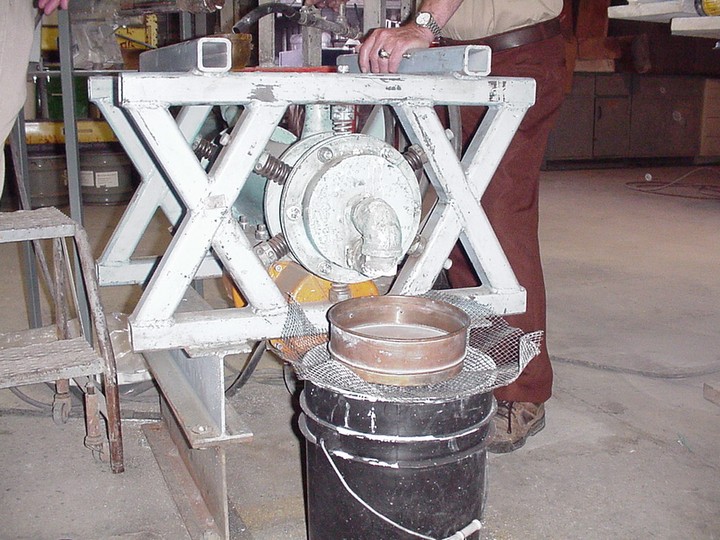
Figure 5. Micro-Grinding test setup.
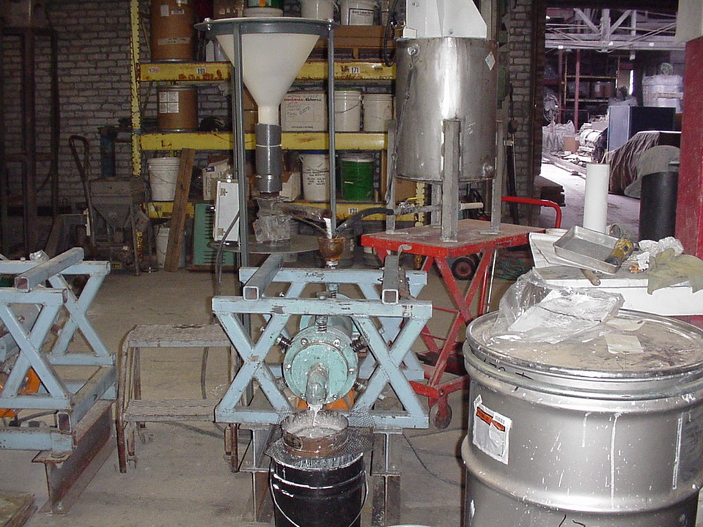
Figure 6. Feeding dry CST and water to the mill.
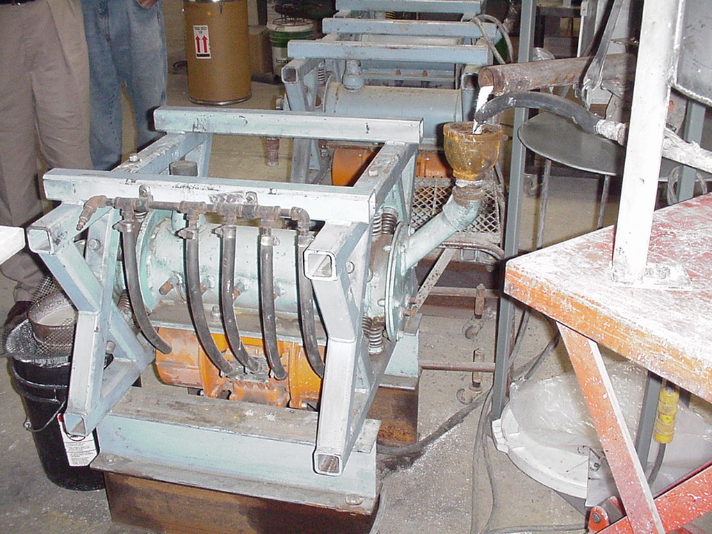
Figure 7. View of inside of test mill showing grinding rods.
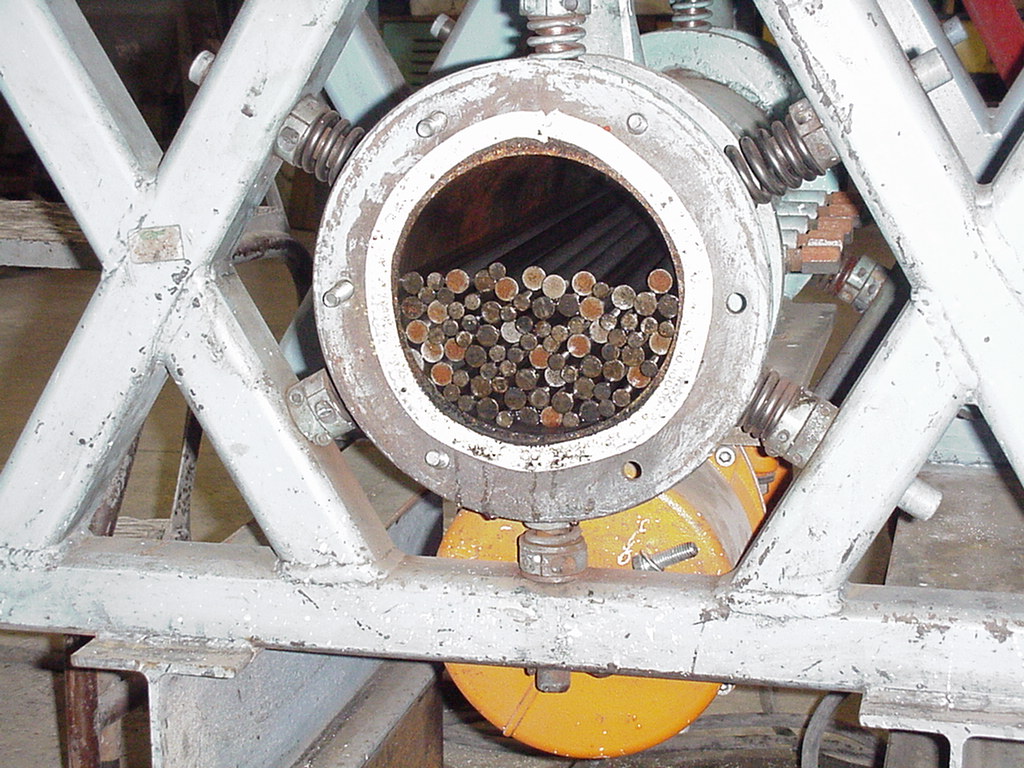
Figure 8. Inside view of mill end plate showing blanked off screen.
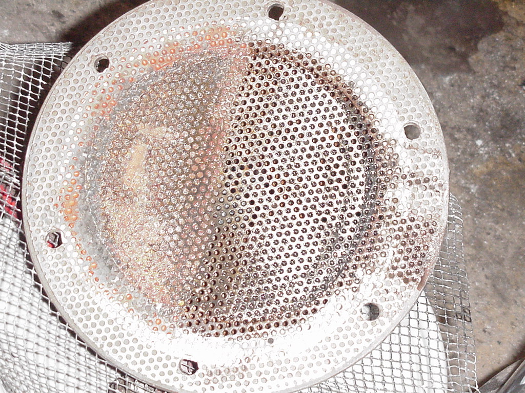
Figure 9. Particle size distribution of CST product from 177 mm test at Micro-Grinding.
Figure 10. Particle size distribution of CST product from 20 mm test at Micro-Grinding.
Figure 11. Micro-Grinding Systems sketch of West Valley equipment installation.
APPENDIX
VENDOR INFORMATION ON IKA DISPAX REACTORÒ