WSRC-TR-2000-00206
Flood Hazard Recurrence Frequencies for A-, K- and L-Areas,
and
Revised Frequencies for C-, F-, E-, S-, H-, Y- and Z-Areas
K. F. Chen
Westinghouse Savannah River Company
Aiken, SC 29808
This report was prepared as an account of work sponsored by an agency of the United States Government. Neither the United States Government nor any agency thereof, nor any of their employees, makes any warranty, express or implied, or assumes any legal liability or responsibility for the accuracy, completeness, or usefulness of any information, apparatus, product or process disclosed, or represents that its use would not infringe privately owned rights. Reference herein to any specific commercial product, process or service by trade name, trademark, manufacturer, or otherwise does not necessarily constitute or imply its endorsement, recommendation, or favoring by the United States Government or any agency thereof. The views and opinions of authors expressed herein do not necessarily state or reflect those of the United States Government or any agency thereof.
This report has been reproduced directly from the best available copy.
Available for sale to the public, in paper, from: U.S. Department of Commerce, National Technical Information Service, 5285 Port Royal Road, Springfield, VA 22161, phone: (800) 553-6847, fax: (703) 605-6900, email: orders@ntis.fedworld.gov online ordering: http://www.ntis.gov/support/ordering.htm
Available electronically at http://www.osti.gov/bridge/
Available for a processing fee to U.S. Department of Energy and its contractors, in paper, from: U.S. Department of Energy, Office of Scientific and Technical Information, P.O. Box 62, Oak Ridge, TN 37831-0062, phone: (865 ) 576-8401, fax: (865) 576-5728, email: reports@adonis.osti.gov
Abstract
Department of Energy (DOE) Order 420.1, Facility Safety, outlines the requirements for Natural Phenomena Hazard (NPH) mitigation for new and existing DOE facilities. The NPH considered in this report is flooding. The facility-specific probabilistic flood hazard curve defines as a function of water elevation the annual probability of occurrence or the return period in years. Based on facility-specific probabilistic flood hazard curves and the nature of facility operations (e.g., involving hazardous or radioactive materials), facility managers can design permanent or temporary devices to prevent the propagation of flood on site, and develop emergency preparedness plans to mitigate the consequences of floods. Methods were developed to determine the probabilistic flood elevation curves for Savannah River Site (SRS) facilities. This report presents the methods used to determine the probabilistic flood elevation curves for A-, K-, C-, F-, E-, H-, S-, Y-, Z- and L-Areas.
1. Background
Flooding can cause structural and non-structural damage, and interrupt critical functions, resulting in huge economic losses. More importantly, if the affected facility contains hazardous or radioactive materials, flooding may result in a significant environmental and health hazard. DOE Order 420.1, Facility Safety, outlines the requirements for Natural Phenomena Hazard (NPH) mitigation for new and existing DOE facilities. Specifically, NPH includes flood events. The facility-specific probabilistic flood hazard curve defines as a function of water elevation the annual probability of occurrence or the return period in years. It is required to determine the flood elevations as a function of return period up to 100,000 years for Savannah River Site (SRS) facilities. Based on facility-specific probabilistic flood hazard curves and the nature of facility operations (e.g., involving hazardous or radioactive materials), facility managers can design permanent or temporary devices to prevent the propagation of flooding on site, and develop emergency preparedness plans to mitigate the consequences of floods. The flood hazard curves for A-Area due to Tims Branch basin runoff, K-Area due to Pen Branch basin runoff, and L-Area due to L-Lake flooding are presented in this report. This report also presents revised flood hazard curves for C-, F-, E-, H-, S-, Y- and Z-Areas due to runoff from the Upper Three Runs Creek and Fourmile Branch basins.
2. Methodology
A straightforward way to determine probabilistic flood hazard curves is to conduct statistical analyses based on measured stream flow records. However, there are two reasons that the SRS stream flow records could not be used for flood hazard analyses. One is that the historical flow records include the effects of significant quantities of cooling water discharged from five SRS production reactors that operated for many years. The other is that the record periods (several decades) are too short to calculate a 100,000-year return flood. To address this, a basin hydrologic routing method was employed. The method in Reference 1 is followed for this study except the calculations for design hyetographs, as discussed in Section 3.1. In addition, a reservoir routing method that was not used in Reference 1 was used for the L-Area flooding study. The method is reviewed next.
Step 1. Hyetographs (rainfall depth or intensity as a function of time) for various return periods were synthesized based on rainfall intensity-duration-frequency data.
Step 2. The Hydrologic Modeling System computer code (HEC-HMS) [2] was used to calculate basin peak flow based on the hyetograph for a given return period and given basin properties. The method used to determine the HEC-HMS input parameters for a basin runoff simulation is presented in Section 2.1.
Step 3. The peak flow calculated by HEC-HMS (Step 2) was then used in the Computer Model for Water Surface Profile Computations (WSPRO) [3] to calculate the flood water elevations. WSPRO was developed by the United States Geological Survey (USGS) for the Federal Highway Administration. WSPRO uses a step-backwater analysis method to calculate water surface elevations for one-dimensional, gradually-varied, steady flow through bridges and overtopping embankments. This step was modified for L-Area water elevation calculations as described in Section 3.5.
Step 4. Steps 2 and 3 were repeated for each return period.
Steps 1 through 4 were applied to Tims Branch, Pen Branch, Upper Three Runs Creek, and Fourmile Branch basins except for the L-Area study. The flood elevation for L-Area is influenced by the L-Lake water elevation. Factors determining the L-Lake elevation during a severe storm include initial lake level, surface runoff to the lake, direct rainfall to the lake, discharge through the L-Lake dam gates, and the lake storage-elevation relationship. Therefore, a reservoir routing model was used in Step 3 for the L-Area flooding study that is described in Section 3.5. The next section describes the procedures to obtain the HEC-HMS input parameters that are used in Step 2 to calculate basin peak flows.
2.1. HEC-HMS Model
HEC-HMS is a hydrologic modeling system developed by the US Army Corps of Engineers, Hydrologic Engineering Center, to model flood hydrology. HEC-HMS performs precipitation-runoff simulations. The HEC-HMS input data are precipitation and model parameters (i.e., losses, runoff transformation and base flow) characterizing the basin properties. The output of HEC-HMS is basin runoff discharge. The input parameters for the basins were determined by matching the HEC-HMS output runoff discharge with the measured runoff discharge for the selected historical storm events. In this report, "basin runoff discharge" means the total volumetric flow rate in the creek, stream, or river.
2.1.1. Measured Storm Event Hourly Rainfall
The data on rainfall within SRS were recorded via a rain gauge network. There are 13 rain gauge stations distributed inside SRS, as shown in Figure 1. Measurements are taken once a day (usually at 6 AM), except for the rain gauge at the Central Climatology Facility. The rain gauge reading at Central Climatology Facility is taken once every fifteen minutes.
The basin-average hourly precipitation is required to calculate basin runoff. The procedure used to convert the daily measured precipitation to basin-average hourly rainfall is presented next.
Step A. The average of the measured rainfall for a given storm event from the gauge stations that cover the basin was taken to be the average rainfall of that storm for the basin.
Step B. The 15-minutes rainfall measurements from the Central Climatology Facility were converted to hourly rainfall.
Step C. The rainfall distribution from Step B was normalized by total rainfall.
Step D. The basin-average hourly precipitation was obtained by multiplying the values from Step A and Step C.
2.1.2 Measured Flows
The measured hourly flows used to determine the HEC-HMS input parameters were provided by the USGS, Columbia, SC District. The USGS maintains a network of monitoring stations at strategic locations on the Savannah River and SRS streams, and at SRS outfalls, to measure the flows, fluid temperatures, and stage highs.
2.1.3. Determination of HEC-HMS Input Parameters
The HEC-HMS input parameters are basin drainage area, loss rate, transform, and base flow. The basin drainage area was obtained from the USGS Water Resources Data book [4]. The area within a basin that is impervious to rain infiltration was estimated from the site map using the ArcView GIS system [5]. The parameters for loss were adjusted to match the measured peak flow. The parameters for the runoff transform model were adjusted to match the shape of the measured hydrograph, and the base flow model parameters were adjusted to match the measured base flow. The resulting parameters were then used by HEC-HMS to calculate basin peak flow using the design precipitation hyetographs derived by Section 3.1.
The calculated results for Tims Branch, Pen Branch and L-Lake are presented in this report. This report also presents the revised results for Upper Three Runs Creek and Fourmile Branch basins. The original calculations for Upper Three Runs Creek and Fourmile Branch basins are in Reference 1. Figure 1 shows the SRS map pertinent to this study.
3.0 Calculations
Calculations for the flood elevations as a function of return years are presented in this section.
Design Hyetographs for SRS
The design precipitation hyetographs specific to SRS were developed based on historical data at or near SRS. The extreme point rainfall as a function of return period and the hourly-rainfall distribution for a given storm event was developed based upon historical precipitation data at or near SRS, as presented in References 6 and 7, respectively. The design hyetographs, in Reference 1, were developed using 6-hour storm events. In addition, the rainfall intensities were reduced based on the assumption that the area averaged rainfall intensity would be lower than the point rainfall intensity. To be conservative, the design hyetographs in this study were developed using 24-hour storm events and no rainfall intensity reductions were applied.
The hourly rainfall for a given return period storm at SRS is calculated by Equation 1.
![]() (1)
(1)
where:
Iij = rainfall (inches) in hour "i"
(i=1, 24) and for j-year return period,
Rj = total 24-hour storm rainfall (inches) for j-year
return period, obtained from Reference 6,
Fi = fraction of rainfall in hour "i" for
a 24-hour storm, obtained from Reference 7.
Table 1 presents the design precipitation hyetograph at SRS for various return periods. The Upper Three Runs Creek and Fourmile Branch basins studies in Reference 1 were revised using these new design hyetograpghs.
Section 3.2 presents the method used to calculate the Tims Branch basin peak flow based on the design precipitation hyetographs derived in Section 3.1.
3.2 Tims Branch Basin
The Tims Branch drainage basin is about 18.86 square miles, most of which lies within SRS. Tims Branch drains much of the M- and A- Areas. This stream flows south-southeast into Upper Three Runs Creek and has a gradient ranging from 10 to 30 ft/mile. The valley is V-shaped with the sides varying from fairly steep to gently sloping. The floodplain is up to 1,000 feet wide. Water flow measurements were recorded on Tims Branch near the confluence of Tims Branch with Upper Three Runs Creek (station 02197309) between March 1974 and November 1982 and from May 1984 to the present.
3.2.1. Tims Branch Basin Runoff Model
Based on historical available storm and flow records, a storm event that occurred on 3/29/91 was used to determine the HEC-HMS input parameters that characterize the Tims Branch basin. The selected storm was an isolated storm event and there was no rainfall for several days before and after the storm event.
3.2.1.1. Rainfall Measurements for Tims Branch Basin
The procedures described in Section 2.1.1 were used to estimate the hourly rainfall over the Tims Branch basin for the selected storm event. The average of the measured rainfall for a given storm event from the four rain gauges (773A, Barricade 2, 700A, and 200-F) that cover the Tims Branch basin was taken to be the average rainfall of that storm for the basin. Figure 2 shows the basin-averaged hourly rainfall in the Tims Branch basin for the 3/29/91 storm event.
3.2.1.2. Tims Branch Basin Flow Measurements
The measured hourly flows at station 02197309 during and after the storm event are shown in Figure 3. These data were provided by the USGS, Columbia, SC District.
3.2.1.3. HEC-HMS Input Parameters for Tims Branch Basin
The procedures described in Section 2.1.3 were used to determine the HEC-HMS input parameters for the Tims Branch basin, as shown in Table 2. These input parameters for the Tims Branch basin were determined to match the measured flows at gauge station 02197309 for the selected storm event. Figure 3 presents the model hydrographs and the measured hydrographs at gauge station 02197309 for the storm event on 3/29/91.
3.2.2. Tims Branch Basin Floods
The peak flows at station 02197309 for various return-period storms, as shown in Figure 4, were calculated by HEC-HMS using the design precipitation hyetographs derived from Section 3.1 and the input parameters derived from Section 3.2.1.3.
3.2.3. Tims Branch Basin Flood Elevations
The flood elevations of the Tims Branch basin for various flows were calculated by the WSPRO computer code. The data required for WSPRO are flow, boundary condition, channel geometry and losses, and hydraulic characteristics of the bridges and road crossings.
There are five culvert crossings and two breached dams on Tims Branch. Personnel of the USGS, Columbia, SC district surveyed eighteen cross-sections along Tims Branch and synthesized 105 additional cross-sections [8]. The synthesized cross-sections were developed using surveyed cross-section data and 7.5 minute series topographic maps. In addition, elevation data and structural geometry for all bridges were determined. Lanier [8] used these data to set up a WSPRO model to determine the 100-year recurrence-interval flood plain for Tims Branch basin. The cross-sections given by Lanier were extended in both banks to accommodate higher flood flows. The ArcView Geographic Information System was used to obtain the expanded cross-section data. The procedures for culvert analysis in Reference 1 were followed to analyze culvert flows. Figure 5 presents the calculated flood elevations near A-Areas as a function of recurrence intervals. For a 100,000-year return flood, the calculated flood elevation at A-Area is 248.19 feet above mean sea level (msl). The elevation of A-Area is above 350 feet msl. Therefore, the probability of flooding for A-Area is significantly less than 1.0E-05 per year.
3.3. Pen Branch Basin
The Pen Branch basin drainage area is about 22 square miles. Pen Branch follows a path roughly parallel to Fourmile Branch until it enters the Savannah River swamp (Figure 1). The only significant tributary to Pen Branch is Indian Grave Branch, which flows into Pen Branch about 5 miles upstream from the swamp. Pen Branch enters the swamp about 3 miles from the Savannah River, flows directly toward the river for about 1.5 miles, and then turns and runs parallel to the river for about 5 miles before discharging into Steel Creek at about 0.5 mile from its mouth. Indian Grave Branch once received effluent cooling water from K Reactor. Upstream of the K-Area outfall, the Indian Grave Branch flow averages only about 1 cfs, and Pen Branch proper is also a small stream averaging 8 cfs. Since November 1976, a USGS flow recorder has been maintained at SRS Road A-13.2 on Pen Branch (station 02197348). During the period between 1976 and 1986, the flow at this station ranged from a minimum of about 1 cfs during a K-Reactor outage to a maximum of 750 cfs during simultaneous K-Reactor operation and a heavy precipitation event. During the water year 1982, the mean flow rate at this station was 339 cfs, and during the water year 1994 (K-reactor was officially shut down in 1993), the mean flow rate was 50.9 cfs, which shows the effect of reactor cooling water discharges on Pen Branch flow rates.
3.3.1. Pen Branch Basin Runoff Model
Based on historical available storm and flow records, a storm event that occurred on 1/6/95 was used to determine the HEC-HMS input parameters that characterize the Pen Branch basin. The selected storm was an isolated storm event and there was no rainfall for several days before and after the storm event.
3.3.1.1. Rainfall Measurements for Pen Branch Basin
The procedures described in Section 2.1.1 were used to estimate the hourly rainfall over the Pen Branch basin for the selected storm event. The average of the measured rainfall for the given storm event from the four rain gauges (CLM, 100-K, 100-L, and 100-P) that cover the Pen Branch basin was taken to be the average rainfall of that storm for the basin. Figure 6 shows the basin-averaged hourly rainfall in the Pen Branch basin for the 1/6/95 storm event.
3.3.1.2. Pen Branch Basin Flow Measurements
The measured hourly flows at station 02197348 during and after the storm event are shown in Figure 7. These data were provided by the USGS, Columbia, SC District.
3.3.1.3. HEC-HMS Input Parameters for Pen Branch Basin
The procedures described in Section 2.1.3 were used to determine the HEC-HMS input parameters for the Pen Branch basin, as shown in Table 2. These input parameters for the Pen Branch basin were determined to match the measured flows at gauge station 02197348 for the selected storm event. Figure 7 presents the model hydrographs and the measured hydrographs at gauge station 02197348 for the storm event on 1/6/95.
3.3.2. Pen Branch Basin Floods
The peak flows at station 02197348 for various return-period storms, as shown in Figure 8, were calculated by HEC-HMS using the design precipitation hyetographs derived from Section 3.1 and the input parameters derived from Section 3.3.1.3.
3.3.3. Pen Branch Basin Flood Elevations
Within the study area, there are three highway bridges, one railroad bridge, four culverts, and six breached dams or old road beds crossing Pen Branch. Personnel of the USGS, Columbia, SC district surveyed 36 cross-sections along Pen Branch and synthesized 76 additional cross-sections [9]. The synthesized cross-sections were developed using surveyed cross-section data and 7.5 minute series topographic maps. In addition, elevation data and structural geometry for all bridges were determined. Lanier [9] used these data to set up a WSPRO model to determine the 100-year recurrence-interval flood plain for Pen Branch basin. The cross-sections given by Lanier were extended in both banks to accommodate higher flood flows. The ArcView Geographic Information System was used to obtain the expanded cross-section data.
Indian Grave Branch is a major tributary to Pen Branch; it flows into Pen Branch at about 2,500 feet upstream from Road A. K-Area sits at the ridge between Pen Branch and Indian Grave Branch (Figure 1). Therefore, an additional WSPRO model was developed to calculate the flood level for the Indian Grave Branch basin. There were no surveyed cross-sections available for Indian Grave Branch. Fifteen cross-sections were determined from the 7.5 minute topographic maps by using the ArcView Geographic Information System. Therefore, the normal water surface elevation of Indian Grave Branch is used as stream bottom. This approach results in higher flood elevation predictions for Indian Grave Branch basin.
Figure 9 presents the calculated Pen Branch and Indian Grave Branch flood elevations near K-Areas as a function of recurrence intervals. Figure 9 shows that, for low flow cases (high annual probability of exceedance), the flood elevations due to Indian Grave Branch are much higher than Pen Branch, and the flood elevation differences between these two basins decrease as flow increases (recurrence interval increases). The reason is that the Indian Grave Branch cross-sections were derived from the 7.5 minute topographic maps. The lowest elevations for Indian Grave Branch shown in the topographic map are in the flood plains. Therefore, the cross-sections of the main channel of the Indian Grave Branch were not modeled. This is equivalent to assuming that water flows over the flood plain. At low flow conditions, the water, in reality, should flow in the main channel, but the model assumed that water flowed over the flood plain. That is why the calculated flood elevations for Indian Grave Branch are high for the low flow conditions. When flow increases, flow over the flood plain increases and the amount of water flow through the main channel would be small relative to the flow over the flood plain. Thus, the error resulting from the assumption that all water flows over the flood plain decreases when flow increases.
For a 100,000-year return flood, the calculated flood elevation at K-Area is 183 feet above mean sea level (msl). The elevation of K-Area is above 260 feet msl. Therefore, the probability of flooding for K-Area is less than 1.0E-05 per year.
3.4. Revisions for Upper Three Runs Creek and Fourmile Branch Basins
In Reference 1, the design hyetographs were developed from 6-hour storm events. In addition, the rainfall intensities were reduced based on the assumption that the area-averaged rainfall intensity would be lower than the point rainfall intensity. To be conservative, the design hyetographs in this study were developed from 24-hour storm events and no rainfall intensity reductions were applied. The Upper Three Runs Creek and Fourmile Branch basins studies in Reference 1 were revised using these new design hyetographs.
Figure 10 shows the revised flood flows for Upper Three Runs basin at various annual probabilities of exceedance or return periods in years. The revised flood elevations for F-Area, S-Area, and Z- and Y-Areas due to Upper Three Runs Creek basin runoff are presented in Figures 11 to 13, respectively. The probabilities of flooding the facilities at F-, S-, Z-, and Y-Areas are less than 1.0E-05 per year, as presented in Figures 11 to 13.
Figure 14 shows the revised flood flows for Fourmile Branch basin at various annual probabilities of exceedance or return periods in years. The revised flood elevations for C-, F-, E- and H-Areas due to Fourmile Branch basin runoff are presented in Figures 15 to 18, respectively. The probabilities of flooding the facilities at C-, F-, E-, and H-Areas are significantly less than 1.0E-05 per year, as presented in Figures 15 to 18.
3.5. L-Area Floods
L-Area sits at the north end of the L-Lake. Flooding of L-Area is determined by the L-lake water elevation, as shown in Figure 19. L-Lake was constructed in 1985 to function as a cooling water reservoir for L-Reactor at SRS to minimize the thermal damage to the Steel Creek flood plain. L-Lake occupies the middle reach of Steel Creek between SRS Road B at the north end of the lake and just upstream of Highway 125 at the south end of the lake. The L-Lake dam is at the south end of the lake. The top of the dam is at 200 feet above mean sea level and a natural spillway is at 195 feet above mean sea level. Factors that determine the L-Lake elevation during a severe storm include initial lake level, basin runoff to the lake, direct rainfall to the lake, discharge through the L-Lake dam gates, and the lake storage-elevation relationship. Operator action can affect discharge through the L-Lake gates. Ultimately, the lake level is limited by the spillway elevation at 195 feet above mean sea level.
As mentioned earlier, L-Area water elevation is determined by the water elevation of L-Lake. Therefore, a reservoir routing model (HEC-HMS) was used to calculate the lake water elevation as a function of return period in years. HEC-HMS uses conservation of mass law to calculate the storage volume of the lake based on inlet and outlet flows. The inlet flows are basin runoff to the L-Lake and the direct rainfall to the L-Lake. The outlet flow is flow discharged from the gates in the L-Lake dam. HEC-HMS then uses the lake elevation-storage relationship to calculate the water elevation for the calculated storage volume.
The inputs of the HEC-HMS model for L-Lake routing are:
Each of these is discussed below.
3.5.1. Steel Creek Basin (Upstream of L-Lake) Runoff Model
The procedures described in Section 2.1 were used to determine the hydrologic characteristics of the Steel Creek basin upstream of L-Lake.
3.5.1.1. Rainfall Measurements for Steel Creek Basin
The 1/6/95 storm event was selected to determine the basin hydrologic characteristics. The average of the measured rainfall for the 1/6/95 storm event from the 100-L and 100-P rain gauges that cover the studied area was taken to be the average rainfall of that storm for the basin. Figure 20 shows the basin-averaged hourly rainfall in the studied basin for the storm event.
3.5.1.2. Steel Creek Flow Measurements
There are two USGS gauge stations on Steel Creek upstream of L-Lake. Station 021973515 is about 0.8 miles upstream of Road B. Station 02197351 is upstream of the Station 021973515 and measures discharge flow from P-Area facilities. The measurements of station 021973515 include flow discharged from P-Area facilities. Therefore, the basin runoff flow due to the 1/6/95 storm event is the difference of the measured flows between Stations 021973515 and 02197351, as shown in Figure 21. The resulting flow is called the adjusted basin runoff flow at Station 021973515.
3.5.1.3. HEC-HMS Input Parameters for Steel Creek Basin Upstream of L-Lake
The procedures described in Section 2.1.3 were used to determine the HEC-HMS input parameters for the Steel Creek basin upstream of L-Lake, as shown in Table 2. These input parameters were determined to match the adjusted basin runoff flow at Station 021973515 for the 1/6/95 storm event. Figure 22 presents the model runoff flows and the adjusted runoff flows at gauge station 021973515 for the 1/6/95 storm event. Basin runoff flows draining to the L-Lake for various return periods were calculated by using the basin characteristics derived from this section and the design hyetographs from Section 3.1. Figure 23 shows the Steel Creek basin runoff flow to the L-Lake for a 100,000-year return storm event.
3.5.2. Direct Rainfall to L-Lake
The HEC-HMS input for direct rainfall is represented by a hydrograph (flow as a function of time). Rainfall direct to the L-Lake is calculated by Equation 2.
![]() (2)
(2)
where:
Wij = flow (cfs) in hour "i" (i=1,
24) and for j-year return period,
Iij = rainfall (inches) in hour "i" (i=1,
24) and for j-year return period from Equation 1,
A = 1,190 acres (Figure 24), lake surface at a water elevation of 195 feet msl
(Reference 10),
a = 1.008333, a factor converting acre-inch/hour to cfs.
Table 3 presents the direct rainfall expressed as hydrographs for various return periods and Figure 23 shows the direct rainfall to the L-Lake for a 100,000-year return storm.
3.5.3. L-Lake Outlet Flow
Opening gates in the L-Lake dam regulates the discharge flow from L-Lake. Figure 25 (Reference 10) shows the L-lake discharge flow as a function of water elevation for three configurations of gates opening (25%, 50% and 100%).
3.5.4. Relationship between Lake Storage and Lake Water Elevation
HEC-HMS uses the relationship between the water elevation and storage volume to determine the water elevation. The relationship between L-Lake elevation and storage volume is obtained from Reference 10 and presented in Figure 26.
The HEC-HMS simulations are based on the following scenario. Before rainfall, the L-Lake water elevation is at 190 feet above mean sea level and the gates are closed. Rainfall starts after 25 hours of simulation time, at which time the gates are opened. Four gate configurations were simulated. They were 1) gates full closed; 2) 25% opening; 3) 50% opening; and 4) full open.
3.5.5. Hydrographs to Account for Opening Gates
The L-Lake operation manual requires that the L-Lake water level be maintained at 190 feet msl. Therefore, the initial condition for L-Lake before rainfall is 190 feet msl and the gates are closed. In its current version, HEC-HMS can only perform flood routing through an uncontrolled reservoir. This means that HEC-HMS cannot open or close gates during the simulation. HEC-HMS uses the reservoir elevation-outlet flow relationship for a particular configuration of gates opening to determine the outlet flow. To simulate the effects of closed gates before rainfall and opening gates at starting of rainfall, an imaginary inlet flow (shown in Figure 27) was used in the HEC-HMS model. From time zero to 25 hours, the imaginary inlet flow equals the flow discharged from the gates for a particular gate configuration and a lake level of 190 feet above mean sea level. The net outlet flow is zero and the lake level is maintained at 190 feet msl from time zero to time 25 hours. Thus, in terms of lake level, it creates the effect of having the gates closed before rainfall. When rainfall starts at 25 hours, the inlet flow of this imaginary hydrograph becomes zero; thus, there is a net outlet flow based on the configuration of gates opening and the lake level of 190 feet msl. This creates the effect of opening gates at the beginning of rainfall that occurs at 25 hours. From this point in the simulation, the lake inflow is determined from the actual hydrographs from the selected storm as illustrated in Figure 23.
3.5.6. L-Lake Water Elevations
L-Lake water elevations were calculated for the four gate configurations discussed above. Figure 28 shows the simulated L-Lake water elevation for a 100,000-year return storm event. In this simulation, the rainfall was started and the dam gates were opened to 25% after 25 hours of simulation time. When the gates are 25% open, the discharge flow is 450 cfs, and there is a time lag for inlet flow (basin runoff flow and direct rainfall) to build up. For this time period, the discharge flow is greater than the inlet flow, causing the water level to decrease between hours 25 to 29, as shown in Figure 28. Four hours after rainfall inception, the inlet flow exceeds the discharge flow, and the water level increases. After the shower passes, the inlet flow decreases, and the water level decreases when the basin runoff flow becomes lower than the discharge flow.
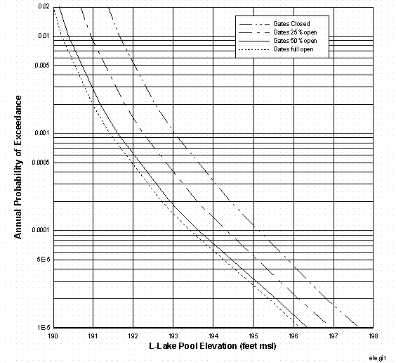
The calculated water levels for L-Lake for various return period of storm events and gates opening configurations are presented in Figure 29. For a same storm event, the calculated maximum water level decreases when the gates opening increases. For the case of 100,000-year -return storm and gates full closed, the calculated maximum water level for L-Lake is 197.64 feet msl. The elevation of L-Area is above 240 feet msl. Therefore, the probability of L-Area flooding is significantly less than 1.0E-05 per year.
4. Conclusions
A method based on precipitation, basin runoff and open channel hydraulics was developed to determine the probabilistic flood hazard curves for Tims Branch and Pen Branch basins near A-and K-Areas respectively. The probabilistic flood hazard curves for Upper Three Runs Creek and Fourmile Branch basins near C-, F-, E-, S-, H-, Y- and Z-Areas were revised by using 24-hour storm events. The probabilistic hazard curves for L-Area were calculated using a reservoir routing model. The calculated results show that the probabilities of flooding at A-, K-, L-, C-, F-, E-, S-, H-, Y- and Z-Areas are significantly less than 1.E-05 per year.
Acknowledgments
The work performed for this project was funded by the U. S. Department of Energy under contract DE-AC09-96SR18500. The author wishes to express special thanks to personnel at USGS, Columbia, SC, district: T.H. Lanier for providing the WSPRO input files and having valuable discussions during the model development; T.W. Cooney, F. Melendez, S.W. Ellisor and B.W. Church for providing the hourly flow records.
References
Table 1. 24-Hour Storm Rainfall Distributions as a Function of Return Period
Return Period (years)
|
50 |
100 |
500 |
1,000 |
5,000 |
10,000 |
50,000 |
100,000 |
|
|
in |
in |
in |
in |
in |
in |
in |
in |
|
|
Hour 1 |
0.035 |
0.039 |
0.052 |
0.058 |
0.074 |
0.082 |
0.103 |
0.114 |
|
Hour 2 |
0.062 |
0.070 |
0.093 |
0.104 |
0.132 |
0.147 |
0.185 |
0.204 |
|
Hour 3 |
0.083 |
0.094 |
0.124 |
0.138 |
0.176 |
0.196 |
0.247 |
0.272 |
|
Hour 4 |
0.242 |
0.273 |
0.361 |
0.403 |
0.515 |
0.571 |
0.721 |
0.795 |
|
Hour 5 |
0.393 |
0.445 |
0.587 |
0.656 |
0.838 |
0.929 |
1.174 |
1.294 |
|
Hour 6 |
0.524 |
0.593 |
0.783 |
0.874 |
1.117 |
1.239 |
1.566 |
1.725 |
|
Hour 7 |
0.725 |
0.819 |
1.082 |
1.208 |
1.544 |
1.712 |
2.163 |
2.384 |
|
Hour 8 |
1.863 |
2.106 |
2.781 |
3.105 |
3.969 |
4.401 |
5.562 |
6.129 |
|
Hour 9 |
1.139 |
1.287 |
1.700 |
1.898 |
2.426 |
2.690 |
3.399 |
3.746 |
|
Hour 10 |
0.628 |
0.710 |
0.937 |
1.047 |
1.338 |
1.483 |
1.875 |
2.066 |
|
Hour 11 |
0.414 |
0.468 |
0.618 |
0.690 |
0.882 |
0.978 |
1.236 |
1.362 |
|
Hour 12 |
0.338 |
0.382 |
0.505 |
0.564 |
0.720 |
0.799 |
1.009 |
1.112 |
|
Hour 13 |
0.117 |
0.133 |
0.175 |
0.196 |
0.250 |
0.277 |
0.350 |
0.386 |
|
Hour 14 |
0.076 |
0.086 |
0.113 |
0.127 |
0.162 |
0.179 |
0.227 |
0.250 |
|
Hour 15 |
0.048 |
0.055 |
0.072 |
0.081 |
0.103 |
0.114 |
0.144 |
0.159 |
|
Hour 16 |
0.035 |
0.039 |
0.052 |
0.058 |
0.074 |
0.082 |
0.103 |
0.114 |
|
Hour 17 |
0.035 |
0.039 |
0.052 |
0.058 |
0.074 |
0.082 |
0.103 |
0.114 |
|
Hour 18 |
0.028 |
0.031 |
0.041 |
0.046 |
0.059 |
0.065 |
0.082 |
0.091 |
|
Hour 19 |
0.028 |
0.031 |
0.041 |
0.046 |
0.059 |
0.065 |
0.082 |
0.091 |
|
Hour 20 |
0.021 |
0.023 |
0.031 |
0.035 |
0.044 |
0.049 |
0.062 |
0.068 |
|
Hour 21 |
0.021 |
0.023 |
0.031 |
0.035 |
0.044 |
0.049 |
0.062 |
0.068 |
|
Hour 22 |
0.021 |
0.023 |
0.031 |
0.035 |
0.044 |
0.049 |
0.062 |
0.068 |
|
Hour 23 |
0.014 |
0.016 |
0.021 |
0.023 |
0.029 |
0.033 |
0.041 |
0.045 |
|
Hour 24 |
0.014 |
0.016 |
0.021 |
0.023 |
0.029 |
0.033 |
0.041 |
0.045 |
|
Accumulation |
6.900 |
7.800 |
10.300 |
11.500 |
14.700 |
16.300 |
20.600 |
22.700 |
Table 2. HEC-HMS Parameters for Basin Runoff Models
|
Table 3 Hydrographs for Direct Rainfall to L-Lake |
||||||||
|
Return Period (Year) |
||||||||
|
50 |
100 |
500 |
1,000 |
5,000 |
10,000 |
50,000 |
100,000 |
|
|
cfs |
cfs |
cfs |
cfs |
cfs |
cfs |
cfs |
cfs |
|
|
Hour 1 |
41.40 |
46.80 |
61.80 |
69.00 |
88.19 |
97.79 |
123.59 |
136.19 |
|
Hour 2 |
74.51 |
84.23 |
111.23 |
124.19 |
158.75 |
176.03 |
222.46 |
245.14 |
|
Hour 3 |
99.35 |
112.31 |
148.31 |
165.59 |
211.67 |
234.70 |
296.62 |
326.86 |
|
Hour 4 |
289.78 |
327.58 |
432.57 |
482.97 |
617.36 |
684.55 |
865.14 |
953.33 |
|
Hour 5 |
471.93 |
533.48 |
704.47 |
786.55 |
1005.41 |
1114.84 |
1408.94 |
1552.57 |
|
Hour 6 |
629.24 |
711.31 |
939.29 |
1048.73 |
1340.55 |
1486.46 |
1878.59 |
2070.10 |
|
Hour 7 |
869.34 |
982.73 |
1297.71 |
1448.90 |
1852.07 |
2053.66 |
2595.42 |
2860.00 |
|
Hour 8 |
2235.44 |
2527.02 |
3336.97 |
3725.74 |
4762.47 |
5280.83 |
6673.94 |
7354.29 |
|
Hour 9 |
1366.11 |
1544.29 |
2039.26 |
2276.84 |
2910.40 |
3227.18 |
4078.52 |
4494.29 |
|
Hour 10 |
753.43 |
851.70 |
1124.68 |
1255.71 |
1605.13 |
1779.84 |
2249.36 |
2478.67 |
|
Hour 11 |
496.77 |
561.56 |
741.55 |
827.94 |
1058.33 |
1173.52 |
1483.10 |
1634.29 |
|
Hour 12 |
405.69 |
458.61 |
605.60 |
676.15 |
864.30 |
958.37 |
1211.20 |
1334.67 |
|
Hour 13 |
140.75 |
159.11 |
210.11 |
234.58 |
299.86 |
332.50 |
420.21 |
463.05 |
|
Hour 14 |
91.07 |
102.95 |
135.95 |
151.79 |
194.03 |
215.15 |
271.90 |
299.62 |
|
Hour 15 |
57.96 |
65.52 |
86.51 |
96.59 |
123.47 |
136.91 |
173.03 |
190.67 |
|
Hour 16 |
41.40 |
46.80 |
61.80 |
69.00 |
88.19 |
97.79 |
123.59 |
136.19 |
|
Hour 17 |
41.40 |
46.80 |
61.80 |
69.00 |
88.19 |
97.79 |
123.59 |
136.19 |
|
Hour 18 |
33.12 |
37.44 |
49.44 |
55.20 |
70.56 |
78.23 |
98.87 |
108.95 |
|
Hour 19 |
33.12 |
37.44 |
49.44 |
55.20 |
70.56 |
78.23 |
98.87 |
108.95 |
|
Hour 20 |
24.84 |
28.08 |
37.08 |
41.40 |
52.92 |
58.68 |
74.15 |
81.71 |
|
Hour 21 |
24.84 |
28.08 |
37.08 |
41.40 |
52.92 |
58.68 |
74.15 |
81.71 |
|
Hour 22 |
24.84 |
28.08 |
37.08 |
41.40 |
52.92 |
58.68 |
74.15 |
81.71 |
|
Hour 23 |
16.56 |
18.72 |
24.72 |
27.60 |
35.28 |
39.12 |
49.44 |
54.48 |
|
Hour 24 |
16.56 |
18.72 |
24.72 |
27.60 |
35.28 |
39.12 |
49.44 |
54.48 |
Figure 1 Savannah River Site Map


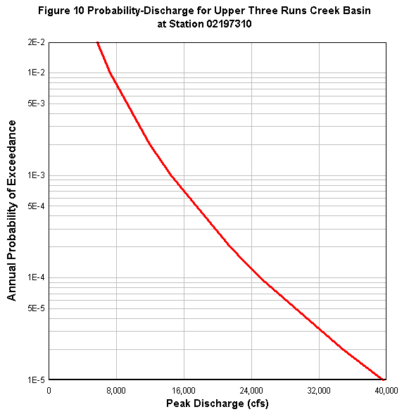
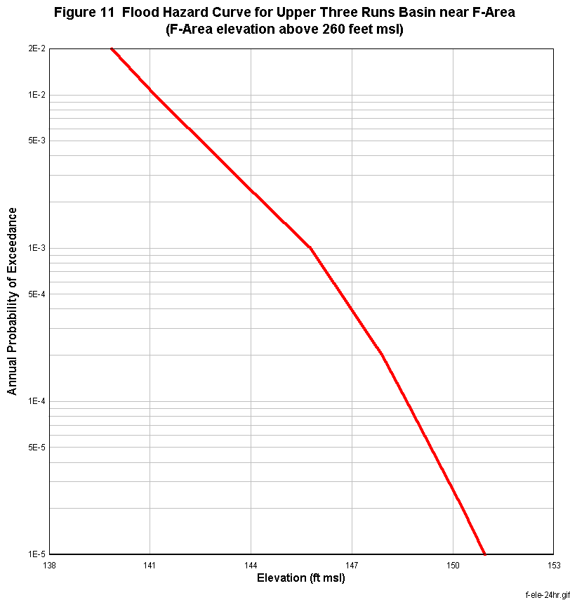


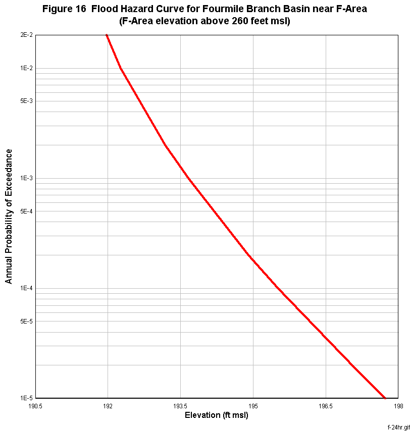
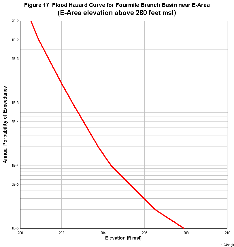

Figure 19 L-Area Flooding Model
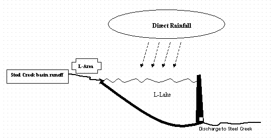
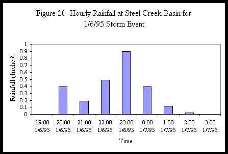
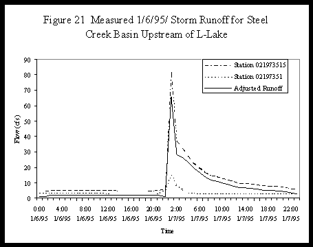


Figure 24 L-Lake Surface Area as a Function of Water Elevation

Reference 10: Project Operations, Steel Creek Dam, Savannah
River Plant, South Carolina,
Operation and Maintenance Manual, VPF 20629-1, U.S. Army Corps of Engineers,
Savannah District, (1986).
Figure 25 L-Lake Discharges as a Function of Water Elevation and Gates Opening

Reference 10: Project Operations, Steel Creek Dam, Savannah
River Plant, South Carolina,
Operation and Maintenance Manual, VPF 20629-1, U.S. Army Corps of Engineers,
Savannah District, (1986).
Figure 26 L-Lake Storage as a Function of Water Elevation

Reference 10: Project Operations, Steel Creek Dam, Savannah
River Plant, South Carolina,
Operation and Maintenance Manual, VPF 20629-1, U.S. Army Corps of Engineers,
Savannah District, (1986).

Figure 28 L-LakeWater Elevation Response to a 100,000-Year Return
Storm
Rainfall starts 25 hours after simulation
Gates 25% opening at Beginning Rainfall

Figure 29 Flood Hazard Curves for L-Area
(L-Area elevation above 240 feet msl)
Gates open at the time of starting shower