WSRC-TR-2000-00036
Plutonium Immobilization – Can Loading
Eric Kriikku and Dr. Gregg Hovis
Westinghouse Savannah River Company
Aiken, SC 29808
This report was prepared as an account of work sponsored by an agency of the United States Government. Neither the United States Government nor any agency thereof, nor any of their employees, makes any warranty, express or implied, or assumes any legal liability or responsibility for the accuracy, completeness, or usefulness of any information, apparatus, product or process disclosed, or represents that its use would not infringe privately owned rights. Reference herein to any specific commercial product, process or service by trade name, trademark, manufacturer, or otherwise does not necessarily constitute or imply its endorsement, recommendation, or favoring by the United States Government or any agency thereof. The views and opinions of authors expressed herein do not necessarily state or reflect those of the United States Government or any agency thereof.
This report has been reproduced directly from the best available copy.
Available for sale to the public, in paper, from: U.S. Department of Commerce, National Technical Information Service, 5285 Port Royal Road, Springfield, VA 22161, phone: (800) 553-6847, fax: (703) 605-6900, email: orders@ntis.fedworld.gov online ordering: http://www.ntis.gov/support/ordering.htm
Available electronically at http://www.osti.gov/bridge/
Available for a processing fee to U.S. Department of Energy and its contractors, in paper, from: US Department of Energy, Office of Scientific and Technical Information, P.O. Box 62, Oak Ridge, TN 37831-0062, phone: (865 ) 576-8401, fax: (865) 576-5728, email: reports@adonis.osti.gov
Abstract
The Savannah River Site (SRS) will immobilize excess plutonium in the proposed Plutonium Immobilization Project (PIP). The PIP adds the excess plutonium to ceramic pucks, loads the pucks into cans, and places the cans into DWPF canisters. This paper discusses the PIP process steps, the can loading conceptual design, can loading equipment design, and can loading work completed.
I. Introduction
Two primary PIP goals are to immobilize surplus plutonium in a ceramic form and store these forms in a high radiation field. The PIP ceramic form makes recovering the plutonium very difficult since it is chemically bonded in the ceramic matrix. The high radiation field makes recovering the plutonium difficult since high radiation fields are lethal to humans. Treaties between Russia and the United States mandate the immobilization and protection of surplus plutonium.
The Plutonium Immobilization Project processing includes preparing the feed streams, converting the metal feed to an oxide, adding the ceramic precursors, pressing the pucks, inspecting pucks, sintering pucks, and moving the pucks between all these processes.
PIP can loading begins with a Cartesian robot. This robot uses a vacuum cup to lift the pucks from the transfer tray and places twenty pucks in a three inch diameter by twenty inch tall metal can. The Cartesian robot places a custom hood on the open metal can. This hood replaces air in the can with helium, and places a plug in the can. Cans are sealed via an automated can welding process, developed at SRS, called ‘bagless transfer.’ After welding, the bagless transfer system lowers the can into an enclosure. A robot in this enclosure swipes the can exterior for contamination and a second robot places the can in a leak detection chamber. If the can passes the swipe and leak detection tests, the robot places it on a transfer cart and sends it to a nondestructive assay (NDA) station. If the can fails either test it is remotely opened and the pucks are reloaded into another can.
After the NDA station, the cans are sent to the magazine loading area. Magazine loading equipment remotely loads four cans into a 3.5 inch diameter by 87 inch long stainless steel magazine. A large bridge mounted robot with a custom manipulator places seven magazines in a DWPF canister. The DWPF canisters are 2 feet in diameter, 10 feet tall, have 3/8 inch thick stainless steel walls, and the top tapers down to a 4 inch diameter hole. Specially prepared DWPF canisters are equipped with an internal rack and latches to accept the seven magazines. Once the canisters are loaded with magazines, they are loaded into a shielded cask and transported to the DWPF. The DWPF began operation in 1997 and this facility mixes high level radioactive waste with glass and pours the mixture into canisters for permanent storage. The DWPF will fill the PIP canisters with high activity waste glass to make the plutonium even less attractive for recovery.
The plutonium to be immobilized generates a large radiation field, so the PIP operations must be performed remotely. The PIP conceptual design uses remote equipment inside shielded gloveboxes to perform operations and glovebox gloves to perform maintenance.
II. Conceptual Design
The following paragraphs describe the PIP can loading conceptual design1. A transport tray of pucks enters the can loading glovebox on a magnetically coupled transport cart, and a tray lift station lifts the tray from the cart. The can loading vision system finds the pucks and tells the robot each puck location. The can loading robot removes the pucks from the tray and loads them in the puck can.
The can loading robot places the helium hood over the puck can and the helium hood seals to the can via an inflatable seal. The helium hood removes the air from the can, fills the can with helium, and inserts the plug into the can. The bagless transfer system welds the plug to the can wall, and cuts the can leaving the can stub in the sphincter seal.
The bagless transfer can holder lowers the can under the glovebox and the swipe robot swipes the can exterior. The can robot removes the can from the bagless transfer can holder, places it in the helium bell jar leak detector to ensure the weld is leak tight. After the leak test is complete, the can robot places the can in a holder on the magnetically coupled transport cart and the can leaves the bagless transfer enclosure.
III. Discussion
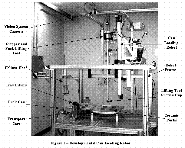
Figure 1 shows the full scale, developmental PIP can loading robot and the following paragraphs describe the can loading equipment design and work completed.
A. Magnetically Coupled Tray Cart and Lifts
The cart design includes permanently mounted rails on the workcell floor, an eight wheeled cart, rare earth magnets mounted to the cart bottom, and a drive system mounted below the workcell floor that moves rare earth magnets parallel to the cart rails 2. The magnets on the drive system attract the magnets mounted under the cart and move the cart along the rails. This allows most of the active, powered parts to be located outside the contaminated environment. Each lift station design includes two linear actuators mounted vertically, a face to face magnetically coupled shaft, and motors mounted below the workcell floor. The magnetically coupled shaft transfers shaft rotation from below the workcell floor into the workcell without a floor penetration or seals. Each linear actuator has a lifting fixture that will grab the puck tray edges. The actuators are constrained to move simultaneously so the tray is kept in the horizontal orientation during the entire move.
The cart and lift work includes integrating the cart and lift actuators to the can loading robot, installing a cart and lift control system, and system testing. The cart and lift system ran 100 cycles without failure 3,4. Each cycle consisted of moving the lift up with a puck tray, moving an empty cart to the lift station, lowering the puck tray onto the cart, moving the cart with tray to elevator position, and moving the cart with tray back to the lift station. The cart position repeatability is +/- 0.002 inches and the lift station repeatability is +/- 0.001. The maximum cart acceleration is 28 inches/second/second and the maximum cart velocity is 45 inches/second. A tray and puck were on the cart during these tests and neither appeared to move or slide. The horizontal force required to decouple the cart from its drive system was measured at 40 pounds. The force is a function of the type, quantity, and orientation of magnets.
B. Can Loading Robot
The robot design includes three linear axes of motion and a gripper. The first axis provides approximately 52 inches of motion in the X direction, the second axis provides approximately 40 inches of motion in the Y direction, and the third axis provides approximately 40 inches of motion in the Z or vertical direction. A DC servomotor drives each axis and an encoder provides position feedback. An industrial computer running Windows NT, Steeplechase, and Citect controls the system and provides an operator interface. The control computer also runs the pneumatic gripper and vacuum system. The gripper is designed to grab 3 inch outside diameter (OD) objects. This allows the gripper to hold bagless transfer can stubs, reject puck cans, and various tools. The puck lifting tool is made from three parts, a suction cup, a 40 inch hollow pipe, and lifting fixture. The suction cup allows the tool to lift the pucks from the top surface and provides a little compliance due to the flexible cup material. This is an advantage since the total puck to can radial clearance is approximately 0.13 inches. The vacuum line runs up the hollow pipe to a fitting on the lifting fixture. The mating fitting is on the gripper and the two are joined when the gripper closes on the tool lifting fixture. The lifting fixture is 3 inches in diameter where the gripper grabs the tool and it has a larger diameter flange above and below the gripping area. The flanges prevent the tool from moving when the gripper is closed on the tool.
The can loading robot work includes the procurement, acceptance tests, and functional testing at SRS. The procurement acceptance test included moving all three axes with a 30 pound load, demonstrating repeatability of each axis to +/- 0.010 inches with a 30 pound load, and automatically loading 20 pucks into a can ten times (200 pucks total) without a failure. The official acceptance tests were completed at the vendor’s facilities and these acceptance tests used metal pucks (3.00 +/- 0.05" OD) and a pipe (3.10 +/- 0.02" ID) for the puck can. The SRS testing began by repeating the 20 puck acceptance test after the robot was delivered and installed at SRS. The remaining robot tests included loading ceramic pucks into a simulated puck can, maneuvering the helium hood onto the puck can, and integrating the vision system, tray cart, and tray lifters.
C. Vision System
The vision system design includes two standard CCD cameras (640 x 480, RS-170 output), a Matrox Pulsar video frame grabber, a Dell 333 MHz computer, Windows 98 operating system, software written in Microsoft Visual C++, and a serial communications link with the robot controller. Once the communications between the robot and vision system are established, the robot asks for a puck location. The vision system acquires an image of the puck trays, finds all the pucks, determines the puck centers, converts the puck center data to robot coordinates using a nnlinear correlation, and sends the coordinates to the robot. The robot then grabs a puck and positions it over a second upward looking camera. The vision system finds the center of this puck and sends small offsets to the robot controller until the puck center is at the camera image center. The robot then loads the puck in the can, moves out of the way, and asks for another puck location. If all the pucks are removed, the vision system tells the robot that no pucks are available.
The vision system work includes assembling the hardware and developing the software. Testing has shown that the single camera above the puck trays does not provide enough resolution to meet the +/- 0.05 inches requirement. The second camera looks up at one puck and has the resolution to meet the +/- 0.05 inch requirement.
D. Helium Hood
The prototype helium hood design includes an inflatable seal to make the seal to the puck can, a chamber, and a taper below the inflatable seal to facilitate puck can alignment. The helium hood function was demonstrated and tested in a helium hood test stand. The test stand actuators move the hood over the puck can and lower it onto the can. The inflatable seal is inflated and a vacuum is pulled to 20 inches of mercury. Air is pumped in the chamber to 3 pounds per square inch since helium is not available. The hollow rod actuator holds the plug in the chamber with a vacuum cup, inserts the plug in the can, and releases the plug.
The helium hood work includes designing the hood, purchasing the test stand, and testing the system. The helium hood test stand demonstrated successful hood operations, and the hood met the design requirements mentioned above. SRS moved the helium hood from the test stand and placed it in the can loading robot workcell. A bracket holds the hood in position to allow the robot to grab and return the hood. A fixture was added to the hood to allow the robot gripper to securely grab the hood and maneuver it over the puck can. The hood air lines and control valves were not included when the hood was moved to the robot workcell due to funding limitations.
E. Bagless Transfer System
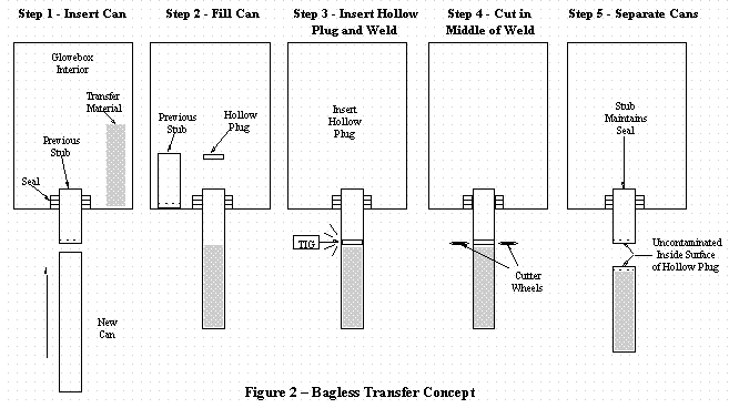
Figure 2 shows the bagless transfer concept, and the following describes the bagless transfer system. The bagless transfer design includes a sphincter seal, TIG welder, pipe cutter, and control system. The bagless transfer system inserts the can into the sphincter seal, the can loading robot places the ceramic pucks inside the can, and the helium hood places the hollow plug into the can. Then the TIG welder welds the can wall to the hollow plug from the outside and the pipe cutter cuts the plug in half at the weld area. The stub remains in the sphincter seal and the can is welded shut.
SRS developed and installed a bagless transfer system in the SRS FB Line facility. The can loading bagless transfer will use the same components, but the can will be 3 inch diameter by 20 inches long instead of the FB Line can dimensions.
F. Swipe Robot
The swipe robot design includes a five axis robot with a gripper, special tooling, and a swipe counter. Once the bagless transfer system completes the welding and cutting processes, the swipe robot grabs a swipe pad and rubs the pad over the can exterior. While the can is in the bagless transfer can holder, the swipe robot can only swipe a portion of the can. The swipe robot loads the swipe pad into a swipe counter and the counter determines if the pad contains contamination. If the pad is clean, the can robot will grab the can where the swipe was taken, remove the can from the bagless transfer holder and present it to the swipe robot. The swipe robot grabs another swipe pad and rubs it over the can top, bottom, and previously unswiped can areas. Again, the swipe robot loads the pad into the counter to verify the can exterior is contamination free.
The swipe robot work includes reviewing the commercial market for small robots and reviewing SRS procedures on swiping. The robot vendor search showed that many commercial systems can perform the swipe robot tasks. The procedure review helped define the swipe robot tasks and thus the robot specifications.
G. Can Robot
The can robot design includes a four axis robot, a gripper, and a can leak detector. The first two robot axes provide linear travel in the X and Y directions at floor level. The third axis provides rotation about the Z axis and the fourth axis provides linear Z motion. The robot gripper uses an electric motor and acme screw to actuate the gripper fingers. The acme screw prevents the fingers from opening if electrical power is lost. The gripper is very strong to grab and support the 25-pound metal puck cans. The can leak detector is a chamber that is large enough to hold a single puck can and has a single door. The can robot loads and can in the leak detector chamber and the door is closed and sealed. A helium detector monitors the chamber gases as a vacuum is pulled on the chamber.
The can robot work includes designing the system, procuring some components, and fabricating some parts. As purchased parts arrive and fabricated pieces are complete, assembly and initial testing will begin.
Acknowledgements
This paper was prepared in connection with work done under DOE Contract No. DE-AC09-96SR18500 with the U. S. Department of Energy. All the PIP Can Loading team members at Lawrence Livermore National Lab and SRS made large contributions to this effort.
References