WSRC-MS-99-00078
Microstructural Characterization of 6061 Aluminum to
304L Stainless Steel Inertia Welds
K. A. Dunn, M. R. Louthan, and M. H. Tosten
Westinghouse Savannah River Company
Aiken, SC 29808
M. L. Birt
Auburn University
Auburn, Alabama
This document was prepared in conjunction with work accomplished under Contract No. DE-AC09-96SR18500 with the U.S. Department of Energy.
DISCLAIMER
This report was prepared as an account of work sponsored by an agency
of the United States Government. Neither the United States Government nor any
agency thereof, nor any of their employees, makes any warranty, express or
implied, or assumes any legal liability or responsibility for the accuracy,
completeness, or usefulness of any information, apparatus, product or process
disclosed, or represents that its use would not infringe privately owned
rights. Reference herein to any specific commercial product, process or
service by trade name, trademark, manufacturer, or otherwise does not
necessarily constitute or imply its endorsement, recommendation, or favoring by
the United States Government or any agency thereof. The views and opinions of
authors expressed herein do not necessarily state or reflect those of the
United States Government or any agency thereof.
This report has been reproduced directly from the best available copy.
Available to DOE and DOE Contractors from the Office of Scientific and
Technical Information, P. O. Box 62, Oak Ridge, TN 37831; prices available from
(423) 576-8401.
Available to the public from the National Technical Information
Service, U.S. Department of Commerce, 5285 Port Royal Road, Springfield, VA
22161.
Abstract
Microstructural characterization of 6061-T6 aluminum-to-Type 304L stainless
steel inertia welds provided a technical basis to conclude that transition
joints fabricated from such welds should satisfactorily contain helium/hydrogen
gas mixtures. This conclusion is based on the lack of semi-continuous
alignments of particles and/or inclusions at, or near, the
aluminum-to-stainless steel interface. These dissimilar metal transition joints
play a key role in the operation of an accelerator driven, spallation neutron
source designed for the production of tritium. The Accelerator Production of
Tritium system will produce tritium through neutron interactions with
3He gas contained in water-cooled, 6061-T6 aluminum pressure tubes.
Current design concepts include thousands of thin-walled pressure tubes
distributed throughout a number of aluminum-clad, lead-filled, blanket modules.
The aluminum pressure tubes are connected to a tritium extraction and
purification system through a stainless steel manifold. The transition from
aluminum to stainless steel is made via transition joints machined from the
aluminum-to-stainless steel inertia welds. The paper describes the baseline
microstructural characterization of the welds, including optical, scanning and
transmission electron microscopy and uses that characterization to evaluate
potential gas leakage across the weld.
Introduction
The Accelerator Production of Tritium (APT) project represents one of several
concepts being evaluated as the potential tritium source necessary to meet the
defense needs of the United States of America. Design, construction and
operation of the, one-of-a-kind APT facility will involve the utilization of a
wide variety of materials that are exposed to unique conditions, including a
high-energy mixed proton and neutron spectra. The target/blanket portion of
the APT system will contain components and structures that have design
lifetimes that range from approximately one to over forty years. Tritium will
be produced through (n,p) interactions with 3He gas that is
contained at approximately 1MPa in pressure tubes fabricated from 6061-T6
aluminum. Thousands of these pressure tubes are distributed throughout the
target/blanket system. The tubes are positioned vertically inside aluminum-clad
lead blanket modules so that cooling water can pass along the outer tube
surfaces. Each tube is connected to the tritium extraction and purification
system through a series of stainless steel manifolds via a transition joint.
The transition joint is machined from a 304 stainless steel to 6061-T6 aluminum
inertia weld. Joint configuration is such that the aluminum side of the
machined joint can be welded to the aluminum pressure tube and the stainless
steel side can be welded into the stainless steel gas distribution manifold.
Anticipated design lifetimes of the pressure tubes are typical of other
components in the target/blanket system. Tubes closest to the tungsten targets
will be replaced about once a year while the outer tubes should not require
replacement. Containment of the helium and tritium gasses in the pressure
tubes must be assured throughout the design life and several approaches have
been used to develop the technical basis for that assurance.
The service life of the 3He pressure tubes may be limited because of
a variety of environmental degradation processes. These processes include: a)
irradiation-induced losses in ductility and toughness, b) corrosion-induced
losses in wall thickness and/or tube wall integrity, c) fatigue-induced crack
growth, and d) synergistic effects among two or more degradation mechanisms.
Each of these effects must be understood and accounted for as service lifetimes
and replacement schedules are developed. The aluminum-to-stainless steel
transition joint is a potential weak link for pressure tube integrity. This
interface could provide a leak path for helium and/or tritium and the galvanic
couple could accelerate corrosion to unacceptable levels. Additionally, there
is little or no data describing the effects of irradiation at the transition
joint. Therefore, an experimental program was established to validate the
performance of the transition joint, and other APT target/blanket materials and
components, under prototypical ATP operating conditions.
Assemblies, designed to evaluate the performance of materials and components
for the APT target/blanket system, were irradiated in a mixed proton and
neutron spectra in test Area-A of the Los Alamos Neutron science Center
(LANSCE). Neutrons were generated by spallation reactions caused by
interactions of the high-energy proton beam with a tungsten target assembly.
The irradiated assemblies included several components that used the
aluminum-to-stainless steel transition joints. The joints were irradiated while
being exposed to cooling water, air and/or helium/tritium gas mixtures.
Evaluation of the irradiated transition joints is currently underway. However,
to provide a baseline for evaluating the irradiated transition joints,
non-irradiated transition joints were characterized by optical and electron
microscopy. Analysis of the distributions of particles at, or near, the weld
interface provided a basis to assess the likelihood for weld-induced leak paths
in the transition joints. The metallographic study also served to develop
sample preparation techniques that were suitable for the hot-cell evaluations
of the irradiated transition joints. This paper summarizes the results of the
baseline evaluation.
Text
Inertia Weld Information
Inertia welding is a process that welds (or joins) two parts by the transfer of kinetic energy from a flywheel to the weld interface. One of the parts is attached to the flywheel and accelerated to a defined rotational speed while the other part is held stationary. When the flywheel and attached part obtain the required kinetic energy (rotational speed), the driving motor is disengaged and the assembly is allowed to rotate freely. The rotating assembly and stationary part are then pressed with an applied axial force [1]. Interfacial friction due to the relative rotation of the faying surfaces breaks up and/or removes surface films, heats the interfacial region and ultimately causes the contacting parts to bond. The
resulting bond is termed an inertia weld.
Inertia welding usually results in short welding times, limited flash and
narrow heat affected zones. The process is particularly useful for joining
dissimilar metals [2]. The heat evolved while making the aluminum-to-stainless
steel inertia welds evaluated in this study was sufficient to discolor the
outer surfaces of the stainless steel sections (Figure 1). The
time-temperature profiles vary with location across the weld interface (Figure
2). The deposition of thermal energy is apparently a minimum at the sample
center and a maximum somewhere between the center and the sample periphery.
The faying surfaces on both the aluminum and stainless steel rods were flat,
except for a machined hole at the center of the steel rod. This hole provided
an internal site for aluminum extrusion during the joining operation (Figure
1). The 6061-T6 aluminum rods used for the test welds had heterogeneous
microstructures with the largest grains located near the rod centerline and the
grain size decreasing toward the rod periphery (Figure 3). The aluminum grain
size had no apparent effect on weld quality as might be anticipated because the
welding operation caused plastic deformation and recrystallization of the
aluminum near the aluminum-to-stainless steel weld interface.
The inertia welds were converted from rod sections into transition joints by
machining the outer surfaces to form a right circular cylinder with the desired
outer diameter and drilling through the rod center lines to form a pipe section
with the desired wall thickness. The transition joints tested in the LANSCE
irradiation were Gas Tungsten Arc (GTA) welded to the appropriate aluminum or
stainless steel sections before testing. Five of the transition joints welded
to 3He pressure tubes and leak tested after being helium filled and
prior to irradiation. Similar joints were given hydraulic burst tests to
confirm weld quality. The hydraulically burst tested joints all failed in
regions of the aluminum that were remote from the weld and heat affected zone
[4]. Non-machined rod samples prepared from the heats of materials used for
the transitions joints irradiated in LANSCE were used for the metallographic
analysis.
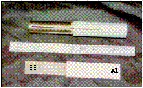
Figure 1. Inertia welded 304L stainless steel to 6061 T6 aluminum
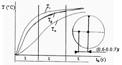
Figure 2. Temperature changes in material at various points during
heating where T is
temperature and t is time. (Note that Tp is
periphery, Tc is center, and Tr
is located at a point
removed from the center at a distance of 0.6-0.7r.) [3]
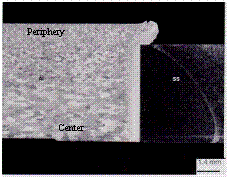
Figure 3. Low magnification photograph of longitudinal cross section of
304L stainless steel to 6061 T6 aluminum inertia weld.
Helium/Hydrogen Containment
Aluminum-to-stainless steel transition joints have been used in helium and hydrogen containment systems for over twenty five years. For example, test systems built in 1974 for measuring tritium permeation through aluminum alloys used an aluminum-to-stainless steel
transition joint [5]. Tritium permeation measurements were made on the tubes by passing a sweep gas over the outer surface of the permeation tube. Permeability measurements with this apparatus were as low as 10-18 cc sec-1 cm-1 atm-1/2. The sweep gas also passed over the transition joint and if tritium had leaked from the joint, low level permeation measurements could not have been made. The initial decision to use the aluminum-to-stainless steel transition joint in the APT target/blanket system was based on this type of experience.
The tubes irradiated in LANSCE were filled with 0.7 MPa 3He. The 3He-tube design and the use of the aluminum-to-stainless steel transition joint were similar to the earlier tritium permeation samples. The 3He-tubes were made by welding a cap on one end of an aluminum pipe section and the transition joint to the other. A stainless steel fitting was welded to the stainless steel side of the transition joint. The fitting was used to pressurize the tube with 3He. Pressurized tubes were sealed with a pinch weld on the stainless steel fitting. Filled tubes were then leak tested. Instrument sensitivity for the leak tests was <1.1E-9 STP cc 4He/sec and no leakage was detected from any of the five tubes tested. The lack of detectable leakage across the transition joint welds was consistent with the results for the earlier tritium permeation experiments and demonstrated that the aluminum-to-stainless steel interface did not provide a significant pathway for gas leakage. Microstructural observations on similar aluminum-to-stainless steel interfaces supported the lack of an apparent leak path.
Specimen Preparation
Samples for baseline analysis were obtained from the Al/SS inertia welded rod by Electrical Discharge Machining (EDM) and sectioning with a standard cutting disk. This EDM cutting method removes material with spark erosion while a wire electrode moves through the material being machined. The electrode wire may be made of copper, tungsten, molybdenum, or brass. For this examination, brass wire was used.
A thin section along the length of the Al/SS rod was obtained by EDM. From this
section, EDM was used to obtain disks with a diameter of approximately 3 mm of
both the parent materials and at the Al/SS interface. Significant surface
cavitation was observed on both the Al and SS following each EDM step. In
addition, the SS section was also discolored following each machining step
(Figures 1 and 4). A sample obtained by both the cutting wheel sectioning and
EDM was analyzed with Scanning Electron Microscopy (SEM) to identify any
effects the sectioning process might have on results from the study (Figure
4).
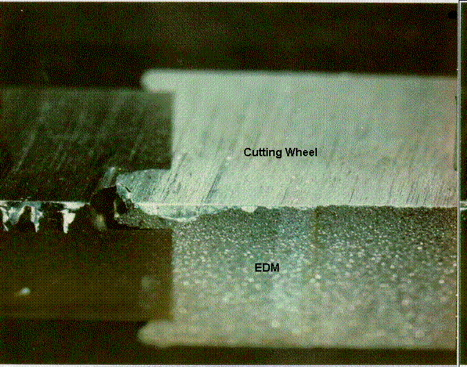
Figure 4. Quartered section of 304L stainless steel cut by both a
cutting wheel and EDM.
SEM confirmed surface cavitation associated with EDM (Figure 5), and Energy
Dispersive Spectroscopy (EDS) identified surface deposits remaining on both the
Al and the SS as a result of the brass wire electrode (Figure 6). The EDS
analysis indicated the presence of Cu and Zn on both the SS and the Al
material. A similar EDS analysis of the surfaces exposed by the cutting wheel,
Figure 7, yielded the expected plots for Al and SS, as shown in Figures 8 and
9. These inertia welded samples were mounted longitudinally and prepared
metallographically. An EDS analysis of the metallographically prepared Al/SS
weld sections did not indicate the presence of any brass wire deposits.
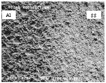
Figure 5. SEM photograph showing the surface cavitation resulting from
the EDM process.
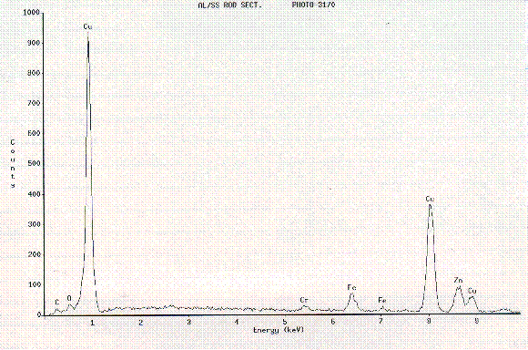
Figure 6. EDS analysis representative of Cu and Zn deposits on both the
Al
and the SS portions of the samples sectioned with EDM.
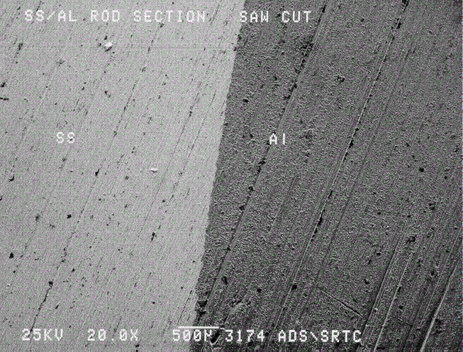
Figure 7. SEM photograph of cut section of inertia weld.
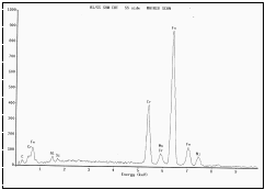
Figure 8. EDS of SS side from cut section.
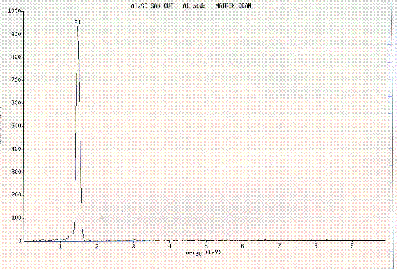
Figure 9. EDS of Al side from cut section.
Metallographic Technique Development and Analysis
Metallographic specimens were prepared by mounting a rod section at the Al/SS weld interface, and a section from each parent metal (Al and 304L SS) away from the weld. The
mounted Al and SS parent materials were ground and polished for etching using
traditional methods for each material. Preparation of the Al/SS interface weld
sample involved complexities inherent to the presence of two dissimilar
materials in the same mount. A sequence of silicon carbide grinding papers and
diamond suspension polishing cloths were coupled with specific values for
application force and working time to develop an appropriate interface sample
(Table 1). The force and time values indicate the compromise necessary to
achieve acceptable quality from preparation of the Al/SS weld specimen.
Table 1. Sample preparation sequence for metallographic analysis.
Grinding/Polishing Sequence |
Prep.
Time (s) |
Application
Force (N) |
500, 600, 800, 1200, 2400 grit
SiC Papers |
90 (Each) |
100,150,100 (Each) |
1 µm Diamond Nap Cloth |
240 |
200, 150, 100 |
6 µm Diamond Nap Cloth |
240 |
200,150,100 |
*Note: Application forces vary among the three listed for each preparation step.
Various etchants for the Al/SS interface sample were tested. The need to
transfer the final process to the CMR hot cells provided criteria such as an
etching sequence that was relatively easy to employ while yielding satisfactory
results. As in the grinding and polishing process, the etching of the Al/SS
interface specimen involved a certain degree of compromise due to the
constituent materials. The etching sequence used involved the application of
Poulton's etching solution for the Al section followed by an electrolytic
oxalic acid solution for the SS (Table 2).
Table 2. Exposure times and compositions of etchants
used in
metallographical analysis.
Poulton's Etching Solution
(Al etchant) |
Oxalic Acid Solution
(SS etchant) |
50 mL Poulton's Reagent*
40 mL chromic acid solution**
25 mL HNO3 |
10 g oxalic acid
100 mL H20
(6V applied to solution) |
Exposure Time: 10 sec. |
Exposure Time: 60 sec. |
*12 parts HCl, 6 parts HNO3, 1 part HF, 1 part H20
**3 g chromic acid per 10 mL H2O
Mounted Al and SS parent metal specimens were also prepared using the etchant
appropriate for each specific metal. Typical microstructures of the base
metals and the inertia welded interface are shown in Figures 10-12. In Figure
10, the observed grain structure indicates that the aluminum alloy was hot
rolled during fabrication as seen by the elongated grains in the mid-section.
The exterior material of the solid Al cylinder appears to have been worked more
extensively than the interior thus leading to the smaller recrystallized
grains. Photographs of the stainless steel parent material, Figure 11, are
consistent with typical Type 304L stainless steel microstructures. Figure 12
clearly shows the microstructural characteristics of the inertia weld. The
flow of aluminum around the welded region and the flash hangover on the samples
is characteristic of the inertia welding process.

Figure 10. Mounted 6061 T6 aluminum parent material showing
elongated grains and recrystallized grains.
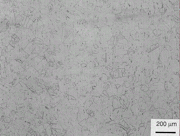
Figure 11. Mounted 304L stainless steel parent material showing normal
behavior.
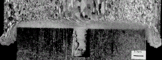
Figure 12. Mounted inertia welded 6061 T6 aluminum to 304L stainless
steel.
Showing the flow of Al material around the SS.
SEM Analysis
Following etching, the Al/SS interface sample was examined with SEM/EDS to evaluate the Al and SS structure along the inertia weld. Examination of the area surrounding the Al/SS interface revealed the appearance of "ditching" along the grain boundaries of the SS material, Figure 13. The "ditching" was also apparent in the SS parent material and is typical of minor amounts of sensitization. The Al alloy appeared to have a dimpling structure throughout the matrix, probably as a result of the etching sequence. Consequently, the inertia weld sample was ground and polished, then re-submitted for SEM/EDS analysis in an unetched condition.
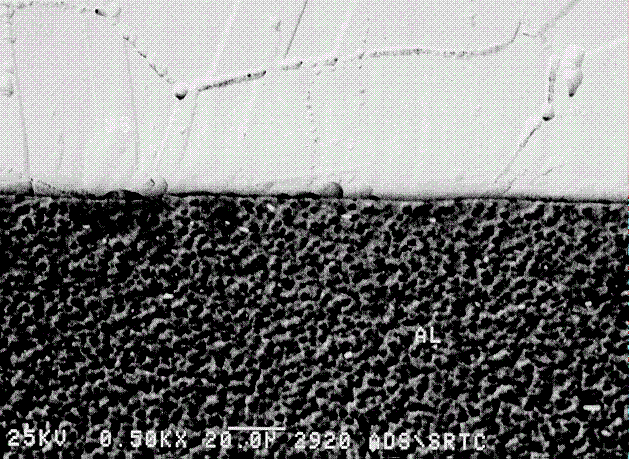
Figure 13. SEM of mounted and etched 6061 T6 Al to 304L stainless steel inertia welded specimen.
SEM examination, using the backscattered electron detector, did not indicate a
pattern of particles along the grain boundaries in the SS material. However, a
small number of particles were observed in the matrix aligned with the rolling
direction, Figure 14. EDS examination of a particle in the matrix revealed the
presence of C, Cr, and Mn with trace amounts of O2 and Al, Figure
15. No impurities in the Al alloy were observed. An EDS analysis across the
unetched Al/SS interface is shown in Figures 16 and 17. A distinct separation
between the Al and SS was seen and no oxides were detected at the interface.
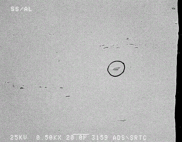
Figure 14. SEM photograph of stainless steel portion of inertia welded
specimen in the unetched condition. Page 28 bottom
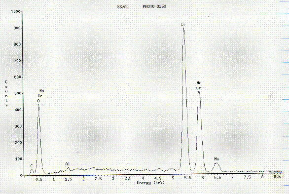
Figure 15. EDS spectrum of particle circled in Figure 14
TEM Analysis
Transmission Electron Microscopy (TEM) was employed to more fully characterize the microstructure of the Al and SS bars - including the HAZ and weld interface regions. With the exception of the interface samples, thin foils were prepared using conventional jet-polishing techniques. (The interface sample was made at LANL using a Gatan Precision Ion Polisher.) The Al samples were prepared using a 25% Nital solution at -20ºC and a
voltage of 35Vdc. The SS samples were made using a 4% perchloric acid, 39%
butylcellosolve, and 57% methanol solution at -30ºC and 35Vdc. All foils
were examined using a JEOL 2010 equipped with a Kevex Sigma EDS system.
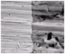
Figure 16. "SEM photograph of mounted and unetched Al/SS inertia
weld.
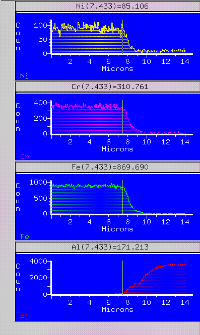
Figure 17. EDS scans for Fe, Cr, Ni, and Al across surface of mounted
and unetched Al/SS inertia weld shown in Figure 16.
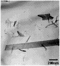
Figure 18. Stacking faults and dislocations in SS base material.
The microstructure of the SS was typical of annealed austenitic stainless steel
(Figure 18). Numerous stacking faults, annealing twins, and a very low
free-dislocation density were observed. TEM did not reveal the presence of any
precipitate species in this material.
The base microstructure of the Al consisted of large, seemingly, equi-axed
grains containing a high dislocation density. All foils contained a low number
density of 1-2µm sized Si, Mg, and O-containing particles. These
inclusions were randomly distributed throughout the material. A coarse
constituent phase containing Al, Fe and Si was also observed (Figure 19). This
phase was more numerous than the oxide phase and was also observed throughout
the Al matrix. Because of limited diffraction data this phase was not
identified, however, a constituent phase with similar morphology, namely,
 -Al12Fe3Si was identified in alloy 6061 by Jenski [6]. For clarity purposes the Al, Fe, and Si phase identified in the current
study will be identified as
  (AlFeSi).
The most abundant precipitate species in the base material was a rod-like
dispersoid measuring 0.1 to 0.3µm in size (Figure 20). This phase was
observed in the Al matrix, on grain boundaries and, in some cases at the
 (AlFeSi)/matrix interface i.e., the
  (AlFeSi) served as a nucleation substrate for the "dispersoid" phase (e.g., at arrow in Figure 19).
This phase contained Al, Fe, Cr, Si, Mn, and Cu and indexed consistently as a
body-centered cubic (bcc) phase with a lattice parameter (ao) of
approximately 12.68Å. A phase containing Fe, based on
Al9Mn2Si1.8 identified by Copper and Robinson
[7], was observed in alloy 6013 by Jenski et al. [8]. Although the
stoichiometry was never determined, the
  (AlFeMnSi) phase in alloy 6013 was bcc with ao=12.68Å.
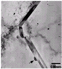
Figure 19. Large  (AlFeSi) constituent particles in the Al.
Additionally, Jensky [6] reported the presence of
 -Al12(Fe,Cr)3Si dispersoids in a alloy 6061 (modified with Cr) with a bcc crystal structure and ao = 12.6Å. The phase observed in the present study may be a modified form of the above phases with the additions of Mn and Cu.
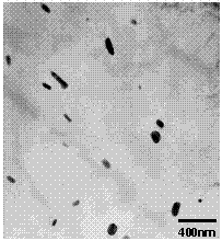
Figure 20. Dispersoid phase in the Al matrix.
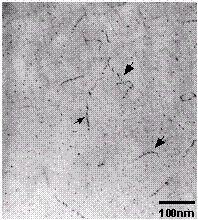
Figure 21.  ' precipitates in the Al matrix.
The last precipitate species observed in the Al base material is imaged in
Figure 21. This phase formed in the matrix <100> and was present as
small needles (or parallelepipeds). The morphology and precipitate orientation
is consistent with this phase being  ', the Mg2Si intermediatephase [9]. This precipitate species also formed on matrix dislocations in a slightly more "blocky" morphology than within the Al matrix (e.g., at arrows in
Figure 21).
  ' precipitate-free zones were also observed at the high
angle boundaries in this alloy.
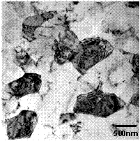
Figure 22. Grain structure in Al HAZ.
In the Heat Affected Zone (HAZ) of the inertia weld, approximately 100µm
from the interface, the grain size was much smaller than the base material
(Figure 22). Grain diameters ranged from 1-2µm in diameter. Similar to
the base material, large Si, Mg, and O-containing particles and the
 (AlFeSi) constituent phase were observed in the HAZ. Additionally,
large, amorphous SiO2 particles were found in the matrix. The bcc
dispersoid phase observed in the base material was also present in the HAZ.
Another precipitate phase, nearly as numerous as the bcc dispersoid phase, was
observed in the HAZ. This phase contained Al, Si, Mg, and Cu and was
distributed randomly throughout the matrix (Figure 23). Similar to the bcc
dispersoid phase, it appeared to be mostly rod-shaped but the size of the
particles was much smaller, i.e., <0.1µm. This phase was very weakly
diffracting making identification impossible. However, the phase composition
is similar to that of the Q phase which can form in Cu-bearing 6XXX alloys [8].
It is interesting to note when particles of this phase intersected the foil
surface they oxidized upon contact with, presumably, the jet-polishing
solution. This resulted in oxide eruptions on the surface of the thin foils.
Two of these oxidized precipitates can be seen at the arrows in Figure 23. The
dark center is the region where the precipitate remains and the lighter annulus
is the oxide residue. No evidence of the  ' phase was observed in the HAZ.
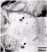
Figure 23. Al, Si, Mg, Cu phase in the Al HAZ.
The interface region can be seen in Figure 24. The interface was reasonably
flat with no mixing of Al and SS. This was confirmed by EDS analysis on both
sides of the interface. The Al microstructure (grain size, precipitate
distribution, etc.) immediately adjacent to the interface appeared the same as
in the HAZ. The SS side of the interface was characterized by a very fine
polycrystalline microstructure extending approximately 1µm into the
stainless steel base before gradually returning to the nominal SS grain size.
The grains in this region measured from about 30 to about 100nm in diameter and
were slightly pancaked parallel to the interface.
Precipitates were observed to have nucleated on the interface (e.g. at A in
Figure 24) and subsequently grown into the Al matrix. EDS analysis indicated
that these precipitates had the same composition as the bcc dispersoid phase
observed in the base alloy and HAZ. One further item of note is that there
appeared to be a 3-5nm thick, discontinuous amorphous "film" along the Al/SS
boundary in some regions (at arrows in Figure 24). Subsequent EDS analysis
indicated this narrow region may have been enriched in oxygen.
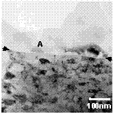
Figure 24. Weld interface. The Al is at the top and SS is at the
bottom in this image.
Summary and Conclusions
The 6061 T6 Al inertia welded to 304L samples were shown to exhibit clean, well
bonded interfaces. SEM and TEM results indicate little mixing of the materials
and few precipitates along the bond interface. These interfacial and near
interface microstructures do not contain inclusion or precipitate morphologies
that would suggest the presence of a leak path along the interface. The lack
of such a path was confirmed by leak testing of 3He filled pressure
tubes.
A grinding, polishing and etching technique developed for the unirradiated
Al/SS inertia weld was integrated into the analysis of the irradiated Al/SS
inertia welds that are located at the LANL CMR hot cells. This metallographic
preparation technique for the Al/SS inertia welded samples provides an
effective baseline characterization to which the irradiated samples can compare
to determine any possible effects on the materials from the irradiation
process.
Acknowledgments
The authors would like to acknowledge J.R. Durden, C.N. Foreman, and D.Z. Nelson of
Westinghouse Savannah River Company for their assistance with this project. In
addition, the authors would like to acknowledge Jose' Velez of North Carolina
State University and S. Maloy of Los Alamos National Laboratory for their
assistance in obtaining TEM specimens for analysis.
References
- Welding Handbook: Welding Processes, "Friction Welding",
8th Edition, pp. 740-761, O'Brien, R.L., American Welding Society,
1991
- Spindler, D. E., What Industry Needs to Know about Friction Welding,
Welding Journal, pp. 37-42, March 1994
- V. R. Ryabov on Welding of Aluminum Alloys to Steels, pp. 67-69,
Harwood Academic Publishers, Ottawa, Canada, (1988)
- Wadleigh, A.S., Bi-Metal Welding of Aluminum, Interface Welding,
Carson, CA
- M. R. Louthan, Jr., G. R. Caskey, Jr., and A. H. Dexter, Hydrogen
Effects in Aluminum Alloys, Radiation Effects and Tritium Technology for
Fusion Reactors, Vol. IV, p. IV-117, CONF-750989, Oak Ridge National
Laboratory, 1976
- Jenski, R. A., Jr., Effects of Cr Addition on the Microstructure and
Mechanical Behavior of 6061-T6 Continuously Cast and Rolled Redraw Bar,
Mater. Sci. Eng. A 237, pp. 52-64, 1997.
- Cooper, M. and Robinson, K., The Crystal Structure of the Ternary Alloy
[alpha](AlMnSi), Acta Cryst., vol. 20, pp. 614-17, 1966.
- Jenski, R. A., Jr., Thanaboonsombut, B., and Sanders, T. H., Jr., The
Effect of Iron and Manganese on the Recrystallization Behavior of Hot-Rolled
and Solution-Heat-Treated Aluminum Alloy 6013, Metallurgical and Materials
Transactions A, vol. 27A, pp. 19-27, 1996.
- Smith, W. F., The Effect of Reversion Treatments on Precipitation
Mechanisms in an Al-1.35 at. pct Mg2Si Alloy, Metall. Trans., vol.
4, pp. 2435-40, 1973.


 -Al12Fe3Si was identified in alloy 6061 by Jenski [6]. For clarity purposes the Al, Fe, and Si phase identified in the current
study will be identified as


 ' precipitates in the Al matrix.

