WSRC-MS-2003-00300
Thermal
Analysis and Test Results for the Overpack
of a TypicalRadioactive Materials Package
Westinghouse Savannah River Company
Aiken, SC 29808
Abstract
In the course of the development and certification of the 9975 Package, extensive thermal analyses were performed and the package subjected to the regulatory HAC thermal test. The results of the thermal analysis and materials tests of the cane fiberboard overpack material were evaluated in comparison with the package HAC thermal test results. The evaluation confirmed that the thermal analysis correctly predicted the performance of the 9975 in the HAC fire test. The post test examination revealed that the heat affected region of the Celotex® overpack correlated well with the calculated temperature distribution.
Background
The 9975 is a drum-type package, consisting of a stainless steel drum outer shell, with an annular, cane fiberboard (Celotex®) insert surrounding and supporting the containment vessels, Figure 1. Unlike most drum type packages, the 9975, which is certified for plutonium contents, has double containment vessels, as required by 10 CFR 71.63, and incorporates a lead shield. The containment vessels employ elastomer O-rings as seals, and their ability to maintain their seal at elevated temperature is the limiting condition for the HAC thermal test. The Celotex® overpack provides both impact protection and thermal insulation for the containment vessels.
In the course of its development and certification, the 9975 has been the subject of thermal analyses and the regulatory HAC fire test. The package subjected to the HAC fire test was instrumented to measure temperatures at various locations during and after the fire. Following the HAC thermal test, the overpack was destructively examined. This paper compares the results of thermal analysis, the fire test and the post test examination.
Thermal Analysis
The thermal analysis of the package was performed to support incorporation of additional contents into the 9975 SARP. The analysis was performed using MSC/Thermal8.5. The fire transient is modeled in two phases, the fire exposure, which lasts for 30 min from the time the package attains the required surface temperature, followed by the cool-down phase, for which the environment temperature boundary condition is changed to 38°C. The model assumed a contents heat generation of 19 watts, for a product container located in the bottom of the containment vessel. The temperature history for the mid-wall location, predicted by thermal analysis for the fire transient, is shown in Figure 2. The temperature contours for 30, 36 and 42 minutes after the fire are given in Figures 3, 4 and 5.
HAC Fire Test
The test package was provided with an internal heater, to simulate internal heat generation (of 22 watts), and instrumented with thermocouples. The heater was located at the top end of the primary containment vessel, overlapping the location of the mid-wall thermocouples. The thermocouples were located at points of particular interest throughout the package. For the purpose of this study of the temperature distribution in the overpack, the locations of interest are the drum, lead and mid-wall fiberboard locations at mid height.
The package was held in a nearly constant temperature environment with the internal heater operating, for five days, to allow the pre-HAC test internal temperature distribution to reach steady state. The heater was maintained at 22 watts during the preheat period. The environment was maintained close to 25°C. The peak temperatures at the locations of interest are shown in Table 1.
Table 1. Peak Steady State Temperatures
|
Location |
Temperature, °C |
|
Drum side |
30.3 |
|
Drum side 180 |
31 |
|
Fiberboard mid wall |
42 |
|
Fiberboard mid wall 180 |
40.3 |
|
SCV Seal |
65 |
|
SCV Seal 180 |
66 |
The HAC thermal test was performed in the Radiant Heat Facility at Sandia National Laboratory. The Radiant Heat Facility employs a battery of external quartz rod heating elements which heat a cylindrical shroud. The shroud surface provides very high, near black body, emissivity. Heater power is controlled to maintain the desired shroud temperature. The acceptance criterion for this facility was maintenance of the drum side temperature at 816°C for 30 minutes.
The 9975 was tested in the vertical position, to provide uniform, benchmark data. As noted above, the package was preheated by its internal heater to steady state prior to the thermal test. The internal heater remained energized (at 22 watts) during the test. Following the 30 min simulated fire exposure, the heating elements were de-energized and the package was allowed to cool for 15 hours, while remaining in the test facility. Temperatures were recorded for 16 hours, from the start of heating. The peak temperature for the primary containment vessel lid occurred 9 hours after the start of heating. The primary containment vessel seals are critical components, are affected by both internal heat generation and external heat input, and exhibit the greatest time lag to attain peak temperature. By the end of the 16 hour test cycle, the outer components were nearing their pre-test temperature.
Table 2. Maximum Temperatures Attained in Thermal Test
|
Location |
Peak
Temperature |
Time
to Peak |
|
Drum side |
816* |
12 |
|
Drum side 180 |
816 |
12 |
|
Fiberboard mid-wall |
166 |
72 |
|
Fiberboard mid-wall 180 |
196 |
62 |
|
SCV Seal |
85 |
380 |
|
Lead outside 180 |
85 |
375 |
|
*Control system set point temperature. Some oscillation occurred during initial heat-up transient. |
||
The mid-wall fiberboard temperature is the result of greatest interest for comparison with the analysis and post test examination of the test package. The temperature history for the two thermocouples at this location is show in Figure 6. The post test examination showed that the mid-wall thermocouple at the 180 position was very close to the char boundary, where the corresponding mid-wall thermocouple was about 1 cm away from the discolored region. This is the reason for the significantly higher temperature at the 180 position.
Post HAC Test Examination
The thermal test package was subject to a thorough destructive examination, following the thermal test. The drum lid was opened and the drum cut away from the overpack. The examination included sectioning the overpack, cutting on a diametral plane, around the lead shield and load distribution plates. Removal of the top plug provided a transverse section at the upper end of the package. The lower section of the Celotex® overpack was separated at the bottom of the interior cavity.
The Celotex® overpack was uniformly charred over its outer surface and reduced in outside diameter by 2 cm, Figures 7 and 8. The inside diameter of the charred region was approximately 35.6 cm, with a char thickness of approximately 4 cm. Assuming the shrinkage in outside diameter is as a result of the charring, the pretest thickness of the char affected zone was approximately 5.2 cm. These dimensions are approximate because the bounds of the charred region are not sharply defined. The discolored region varies from undetectable to fully blackened over a distance of about 1.1 cm. Similarly, the outer surface of the charred material is rough and fissured.
Results of thermal tests reported by Lewallen, and others, indicate that Celotex® degrades thermally for temperatures over a threshold temperature of about 285°F. At temperatures above this threshold, thermal degradation results in progressive darkening of the material. In long term exposure, at constant temperature, slight darkening of the Celotex® was observed at 300°F. Above 300°F discoloration is progressively greater as temperature increases. Based on these results, the temperature at the inner bound of the charred region of the 9975 is estimated to be about 300°F.
Discussion.
The results of the thermal analysis and test were very consistent. The temperatures calculated at mid wall of the Celotex® overpack were consistent with those measured in the thermal test. The mid height Celotex® temperature variation during the fire and post-fire simulations, Figure 2, compares very well with the temperature variation during the test. As shown in Table 2, above, the maximum temperature measured during the test was 166°C. The maximum temperature reached in simulations using boundary conditions specified in 10 CFR 71 for a 19 watt internal heat source is 116°C. The difference is primarily due to the furnace shroud temperature of nearly 871°C, during the fire test, instead of the 800°C used in the calculated results, and the location of the heater at the top of the containment vessel for the test, where the source is at the bottom in the analysis. In addition, the shroud and other components of the radiant heat facility cool more slowly than the instantaneous change in boundary temperature (to 38°C) in the calculational model. The opposite position, where charring was close to the thermocouple, resulted in a measured temperature of 196°C, compared to 116°C, near the boundary of high thermal gradient region. The temperature gradient is very steep in this region, so that small changes in position result in large variation in associated temperature.
The outer region of the Celotex® overpack, where the temperature and thermal gradient are high, corresponds directly to the charred region found during disassembly of the test package, (compare Figures 5 and 8). The measured and calculated temperatures in this region are consistent with the thermal degradation displayed by the Celotex®.
The results confirm the ability of the analytical models to predict thermal response of RAM packages. Significantly, the effect of thermal property variation due to thermal degradation of the Celotex® was a minor effect and did not compromise the ability of the model to predict the temperatures at critical locations.
Acknowledgements
The authors gratefully acknowledge the contributions of S. J. Hensel, who performed the original thermal analysis for the fire test configuration; M. N. Van Alstine; who was task lead for the thermal test and post-test destructive examination; G. Cadelli, for developing information on response of CelotexÒ to heating; R. J. Gromada for his advice and support for the test program; J. Pardo for his invaluable assistance above and beyond his role as QA oversight; and the thermal testing staff of Sandia National Laboratory who were responsible for performance of the thermal tests.
References
- Safety Analysis Report Packages, 9965, 9968, 9972-75 Packages, Savannah River Site Report WSRC-SA-7, Rev.14,
- Lewallen, E. E., Drum and Board Type Insulation Overpacks of Shipping Packages for Radioactive Materials, Savannah River Site Report DP-1292, July 1972.
Figure 1. The 9975 Radioactive Materials Package is a typical drum-type package.
Figure 2. 9975 Mid-Wall Fiberboard Calculated Temperatures.
Figure
3. Temperature Contours in Fiberboard at 30 minutes into the fire transient.
Figure 4. Temperature Contours in Fiberboard at 36 minutes into the fire transient.
Figure 5. Temperature Contours in Fiberboard at 42 minutes into the fire transient.
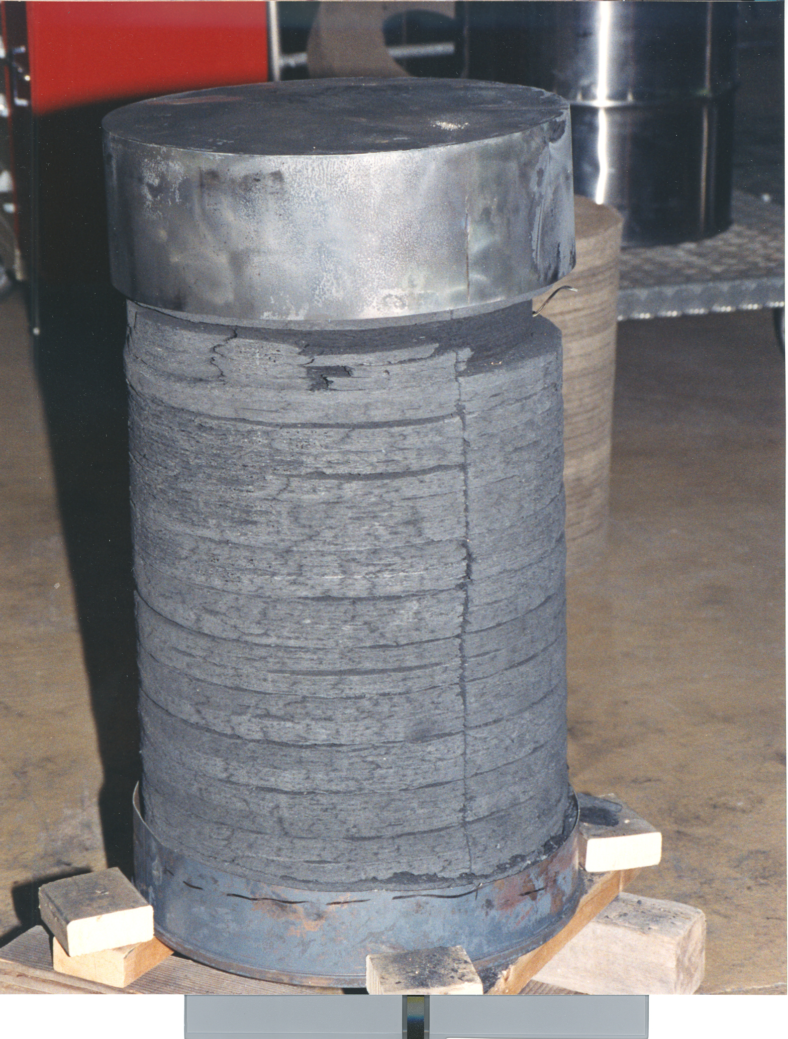
Figure 7. Outer surface of Celotex® overpack following the fire test.
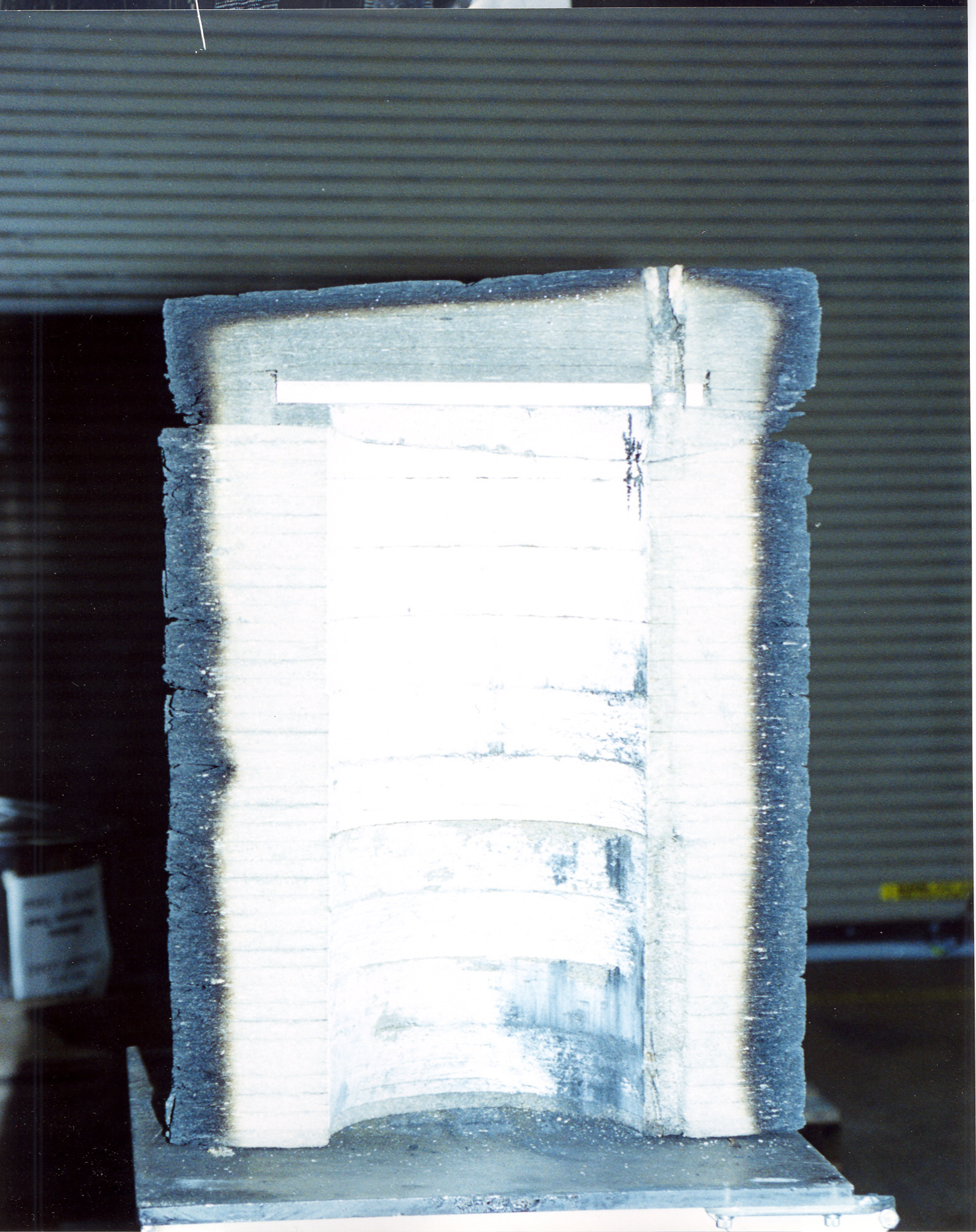
Figure 8. Cross section of Celotex® overpack following the fire test.