WSRC-MS-2001-00201
Demonstration of the Caustic-Side Solvent Extraction Process
for the Removal of 137Cs from Savannah River Site High Level Waste
M. A. Norato, M. H. Beasley, S. G. Campbell, A. D. Coleman,
M. W. Geeting, J. W. Guthrie,
C. W. Kennell, R. A. Pierce, R. C. Ryberg, and D. D. Walker
Westinghouse Savannah River Company
Aiken, SC 29808
J. D. Law and T. A. Todd
Idaho National Engineering and Environmental Laboratory
This report was prepared as an account of work sponsored by an agency of the United States Government. Neither the United States Government nor any agency thereof, nor any of their employees, makes any warranty, express or implied, or assumes any legal liability or responsibility for the accuracy, completeness, or usefulness of any information, apparatus, product or process disclosed, or represents that its use would not infringe privately owned rights. Reference herein to any specific commercial product, process or service by trade name, trademark, manufacturer, or otherwise does not necessarily constitute or imply its endorsement, recommendation, or favoring by the United States Government or any agency thereof. The views and opinions of authors expressed herein do not necessarily state or reflect those of the United States Government or any agency thereof.
This report has been reproduced directly from the best available copy.
Available for sale to the public, in paper, from: U.S. Department of Commerce, National Technical Information Service, 5285 Port Royal Road, Springfield, VA 22161, phone: (800) 553-6847, fax: (703) 605-6900, email: orders@ntis.fedworld.gov online ordering: http://www.ntis.gov/support/index.html
Available electronically at http://www.osti.gov/bridge
Available for a processing fee to U.S. Department of Energy and its contractors, in paper, from: U.S. Department of Energy, Office of Scientific and Technical Information, P.O. Box 62, Oak Ridge, TN 37831-0062, phone: (865 ) 576-8401, fax: (865) 576-5728, email: reports@adonis.osti.gov
ABSTRACT
This paper describes a demonstration of a solvent extraction process for removal of 137Cs from alkaline high level radioactive waste (HLW) solutions from the Savannah River Site (SRS) tank farm. The process employed a calix[4]arene-crown-6 extractant dissolved in an inert hydrocarbon matrix, along with an alkylphenoxy alcohol modifier, and an additional additive, trioctylamine, to improve stripping performance and mitigate the effects of organic anions present in the feed stream. Testing included washing and recycle of the solvent. Tests conducted with two non-radioactive simulants of SRS tank waste verified proper hydraulic operation prior to the radioactive experiments. An additional 12-hour demonstration used simulated SRS tank waste spiked with 137Cs to confirm proper hydraulic operation, decontamination and volume reduction factors following installation of the equipment in a shielded cell facility. Finally, a 48-hour demonstration was performed employing a composite waste from SRS tank farms. Approximately 106 liters of waste (1.5E+09 d/min/mL 137Cs activity) was processed through the test unit. Average 137Cs decontamination factors for the decontaminated waste streams in all tests exceeded the target value of 40,000. Concentration factors in the strip section agreed to within 5% of the target value of 15.
Key Words: Cesium, Waste Processing, Solvent Extraction, Centrifugal Contactors
INTRODUCTION
To meet regulatory and safety requirements, the High Level Waste (HLW) currently stored in tanks at the US Department of Energy’s (DOE) Savannah River Site (SRS) must be emptied and converted into a form that is suitable for long-term storage or discharge to the environment. Suitable waste forms include high level borosilicate glass to be stored at a federal repository, low level saltstone to be stored in vaults at SRS, and decontaminated water suitable for release to the general environment. One major radioactive constituent that must be removed from the waste is 137Cs. The current favored technology for 137Cs removal is Caustic-Side Solvent Extraction (CSSX). The CSSX process uses a countercurrent solvent extraction process to remove the 137Cs from a clarified salt solution that has been pretreated in a strontium and alpha adsorption operation (1).
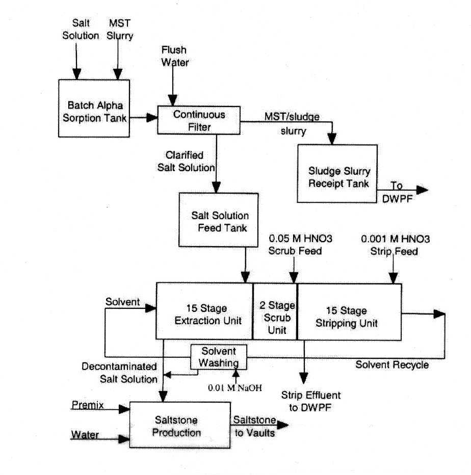
Figure 1 shows the proposed CSSX flowsheet. HLW salt solution and monosodium titanate slurry are mixed in the batch alpha sorption tank and filtered. The solids are sent to vitrification, and the clarified filtrate is sent to the CSSX process. The salt solution enters the 15th (final) stage of the extraction section of the CSSX process and flows countercurrently to the extraction solvent. During the extraction process, 137Cs is transferred to the solvent, and the decontaminated salt solution exits the process for saltstone production. The saltstone product is then placed in permanent storage in vaults at SRS. The cesium-loaded solvent is scrubbed, then the cesium is stripped and concentrated in a countercurrent strip section. The aqueous strip effluent is sent to a vitrification plant, and is converted into a borosilicate product that will be permanently stored at a federal repository. The stripped (clean) solvent is then recycled back to the extraction section.
The solvent extraction process for removal of cesium from alkaline solutions has been developed utilizing a novel solvent invented at the Oak Ridge National Laboratory (ORNL) (2). This solvent consists of calix[4]arene-bis(tert-octylbenzo-crown-6) (BOBCalixC6) extractant dissolved at 0.01 M in an inert hydrocarbon matrix of IsoparÒ L. A modifier, 1-(2,2,3,3-tetrafluoropropoxy)-3-(4-sec-butylphenoxy)-2-propanol, (Cs7SB), is added to the solvent to enhance the extraction power of the calixarene and to prevent third phase formation. An additional additive, trioctylamine, is used to improve the performance during the stripping of cesium from the loaded solvent and mitigate the effects of any lipophilic anions present in the feed stream (3). The chemical structures of the solvent additives are shown in Figure 2.
TEST OBJECTIVES
Although a number of studies using simulated waste solutions had been performed to determine the stability of the extraction solvent system with respect to radiation and chemical exposure to SRS HLW, extended operation with actual SRS waste was necessary. It was essential to verify that the presence of minor components in the waste solutions would not adversely affect extraction or stripping performance.
Therefore, the demonstration at the Savannah River Technology Center (SRTC) had the following objectives (4).
This paper addresses primarily the last four objectives. It should be noted that the mixture of wastes was chosen because blending of waste from various tanks is expected in plant operation. The two tank wastes provided from Tanks 37H and 44F were chosen because they met the requirement for waste from both tank farms and, once diluted, had roughly the desired sodium concentration (5.6 M). The blended waste also had higher than average concentrations of cesium and potassium (which competes with cesium in extraction), as well as higher hydroxide concentrations. The waste of Tank 37H was thought to contain elevated concentrations of noble metals, and the two tank wastes were thought to contain reasonable amounts of organic compounds from the Plutonium-Uranium Extraction (PUREX) process. This blended waste solution was, therefore, suitable for evaluating the process.
TEST APPARATUS CONFIGURATION
The test apparatus centered on 33 stages of 316 stainless steel, 2-cm centrifugal contactors designed and fabricated by Argonne National Laboratory (ANL). The contactors were positioned in a two-tiered arrangement. The upper tier contained one wash stage, 15 extraction stages, and two scrub stages. The lower tier contained the 15 strip stages. There were also two unused stages on the upper tier and one on the lower that contained replacement motor/rotor assemblies. Figure 3 shows a photograph of the test apparatus during non-radioactive checkout.
Liquids were fed to the contactors using pumps manufactured by Fluid Metering, Inc. (FMI). Flow rates in all streams were measured by RheothermÒ flow instruments, with the output signals sent to a computer-based process control system. Also, the feed rates of the waste, scrub, and strip solutions were measured using MettlerÒ balances.
Temperature in the extraction section was maintained below 25 0C by means of stainless steel cooling channels that were welded to the base of the contactor assembly. Chilled water from a computer controlled, LaudaÒ Brinkman Ecoline RE206 circulating bath provided cooling. Type K (Omega Engineering) thermocouples were attached to eight extraction stages, two scrub stages, and eight strip stages to monitor temperature and, in the extraction section, provide feedback input to the control system.
The computer based process control system consisted of a Tri-Star International Star Station EX industrial hardened workstation running Windows NT Workstation version 4.0 and the Intellution FIX32 version 7.0 process control software. Temperature, flow, and balance data were logged to the workstation, and those data were written to the computer hard drive every four hours. The data were also manually archived to compact disk (CD) every 24 hours.
SYSTEM OPERATION AND FLOWSHEET CONDITIONS
Process flow operation is shown schematically in Figure 4. The tank waste or simulant solution was introduced at stage 15 and flowed countercurrent to the solvent. The 0.05 M nitric acid scrub solution was introduced at stage 17 and flowed in the same direction as the waste or simulant. The purpose of the nitric acid scrub is to remove accumulated metals, such as aluminum, potassium or sodium so that they are routed to the low-level waste (LLW) raffinate stream. Also, as the waste or simulant solutions are highly caustic, the scrub serves to lower the pH of the loaded solvent so that the very dilute nitric acid solution used to strip the cesium from the loaded solvent is not neutralized on contact. Furthermore, the pH adjustment also prevents precipitation of aluminum and other metals in the strip section.
Once scrubbed, the cesium-loaded solvent flows to the 15 stages of the strip section where it is contacted in a countercurrent fashion with 0.001 M nitric acid. The strip operation serves to remove cesium from the solvent and concentrate it in an aqueous phase suitable for vitrification. The aqueous phase from the scrub section is mixed with the incoming waste feed and exits the system as part of the decontaminated salt solution that is suitable for processing as a low level waste in the SRS Saltstone facility.
After stripping, the clean solvent flows through a single wash stage where it is contacted with 0.01 M sodium hydroxide. The solvent wash stage serves to remove any compounds that may be a result of radiolytic degradation of the extractant, modifier, or suppressor. After washing, the solvent is recycled back to the extraction section.
The waste or simulant solution flowed through the system at 36 to 43 mL/min and was mixed with scrub solution flowing at 2.8 mL/min. The solvent was fed at 12.8 to 14 mL/min such that an organic-to-aqueous (O/A) flow ratio of approximately 0.3 was maintained.
The solvent flow rate was maintained constant in the strip section, and the strip feed was introduced at flow rates of 2.5 to 2.8 mL/min such that an O/A of approximately 5 was maintained. The wash solution was also fed at 2.8 mL/min maintaining an O/A of approximately 5.
EXPERIMENTAL OPERATIONS
The solvent extraction process was operated with the aqueous phase continuous. That is, the organic phase was dispersed as droplets in the aqueous phase. Each experimental test run was initiated by starting the rotors and filling the wash, scrub, and strip stages with wash (0.01 M NaOH), scrub (0.05 M HNO3), and strip (0.001 M HNO3) solutions, respectively. Once the wash, scrub, and strip feeds were established, cesium-free simulant feed was introduced at stage 15. When steady flow in the extraction section (stages 1- 15) was established, solvent feed to the wash stage was initiated. Once solvent was observed exiting the apparatus at stage 32, the aqueous feed was switched to the cesium-containing test solution.
During test operations researchers monitored motor rotation, liquid levels in the contactor standpipes and decanters, feed and collection tank levels, chiller and flowrate setpoint trends, and instrument outputs. Samples were taken intermittently by placing sample vials at outlet points of continuously flowing streams. Solvent feed samples were not taken to avoid hydraulic disruption of the test apparatus.
At the end of each test, motor rotation and process liquid feeds were stopped as close to simultaneously as possible to minimize disruption to the contents of the individual stages. Individual stage samples were then obtained by draining each stage into polypropylene sample bottles. The equipment was then rinsed. The extraction section was rinsed with 2 M NaOH to prevent precipitation of aluminum hydroxide in the waste. The strip section was rinsed with any remaining strip feed (0.001 M HNO3). After the initial rinse, all stages were flushed with water.
SIMULANT TESTING
Non-Radioactive Simulant Test Results
Before testing with waste from Tanks 37H and 44F was performed, tests were run with simulated high-level waste solutions. These tests were intended to verify proper hydraulic operation of the system as well achievement of desired decontamination and concentration factors. The liquid flow rates for all process fluids in all tests are summarized in Table 1.
One series of tests was performed in the SRTC Shielded Cells mockup facility with an SRS average simulant solution containing non-radioactive cesium (5). The second series of tests was performed after the apparatus was installed in the SRTC Shielded Cells facility and employed SRS average simulant and a simulant of blended waste from Tanks 37H and 44F. Both simulants were spiked with 137Cs. It should be noted that the SRS average simulant represents an average of chemical compositions from all the soluble wastes contained at the SRS tank farms.
The non-radioactive testing was performed by running 15 L of SRS average simulant at 40 to 41 mL/min through the test apparatus in two six-hour tests. The first test experienced several interruptions due to contactor flooding. This was caused by interstage lines that had become bent during transport and assembly of the test apparatus. The bent lines required the organic phase to flow uphill from one stage to the next in the affected stages. Because the head pressure is quite low, the organic liquid was unable to flow uphill and the contactors flooded. After all affected interstage lines were straightened, the test was resumed without interruption. The second non-radioactive test was performed with no interruptions. The results of the non-radioactive simulant tests are shown in Table 2. Due to analytical limits for detecting non-radioactive cesium, the measurable decontamination factor (DF) for the extraction factor was reported to be in excess of 200 for both tests. The concentration factor (CF) for the first non-radioactive simulant test was relatively low prior to the test interruptions. The CF before interruptions ranged from 11.0 to 11.5. After the interstage lines were straightened and the test resumed, the CF averaged 14.3. The average CF for the entire second non-radioactive simulant test was 14.1. The observed extraction efficiency was 86 ± 6% for the two tests, and the observed stripping efficiency was 96 ± 6%.
137Cs Spiked Simulant Test Results
Once the CSSX test apparatus was installed in the highly-radioactive environment of the SRTC Shielded Cells facility, it was necessary to verify that the desired decontamination and concentration factors could be achieved, and demonstrate that relocation of the test apparatus did not adversely affect hydraulic performance. Therefore, further testing was performed using simulants traced with 137Cs. These tests also served as an opportunity to perfect experimental technique in a radioactive environment prior to testing with real HLW. The radioactive simulant testing consisted of two consecutive six-hour tests with simulated HLW solutions spiked with 137Cs. The first test was performed using spiked SRS average simulant, and the second test was performed using Tank 37H/44F simulant. In each case the 137Cs was introduced to the simulant by adding a known amount of actual Tank 37H/44F blended waste solution to achieve the desired 137Cs activity between 5.3 x 10⁶ and 9.6 x 10⁶ d/min/mL.
The first test processed approximately 15 L of spiked SRS average simulant, and the second test processed approximately 13 L of spiked Tank 37H/44F simulant in uninterrupted back-to-back tests. Other than a small amount of emulsion observed in the solvent wash decanter during the first six-hour test, hydraulic performance of the system was excellent.
A summary of spiked simulant test data is shown in Table 2. DF data from the first test (using SRS average simulant) were as high as 200,000 during the first three hours of testing and then declined gradually from four to six hours. When the feed was switched to Tank 37H/44F simulant for the second test the DF values climbed back to about 200,000 during the following two hours. The observed DF values then declined over the remaining four hours of operation to an apparently steady value of approximately 36,000. The observed decrease in DF at nine and ten hours is probably due to sampling errors or contamination as the DF at eleven and twelve hours increased abruptly back to 36,000. Due to detection limits, physical differences between simulants, and possibility of contamination in the Shielded Cells environment, it is difficult to determine whether the observed declines in DF were an actual trend or merely variation in the samples. Averaging of DF values for the first six hours of testing yields an average DF of 43,000 for the SRS average simulant. Similar averaging for the second six hours yields an average DF of 63,000 for the Tank 37H/44F simulant. Both tests yielded an average DF in excess of the target DF of 40,000.
Concentration factors (CF) were observed to be 14.8 for the spiked SRS average simulant and 13.8 for the spiked Tank 37H/44F simulant. These values were both close enough to the target value of 15 to warrant proceeding with the real waste demonstration. As shown in Table 2, extraction efficiencies were determined to be 94 ± 6% for the spiked SRS average simulant and 84 ± 4% for the spiked Tank 37H/44F simulant. Stripping efficiencies for both simulants were approximately 82%.
TANK 37H/44F WASTE DEMONSTRATION
Operations
Over a 65-hour period, the CSSX test apparatus operated for 48 hours and treated approximately 106 L of Tank 37H/44F composite HLW solution. During the first 34 hours of testing an average DF of 511,000 was achieved. The average DF for the entire 48 hours of operation was 40,000. During stable hydraulic operation individual DF values as high as 2,000,000 were achieved. However, there were three interruptions during testing.
The Tank 37H/44F composite waste was derived from liquid radioactive waste samples drawn from Tanks 37H and 44F of the SRS tank farm. These tanks are currently inactive and store mostly saltcake (a mixture of crystallized or precipitated salts) with a layer of concentrated salt solution. Approximately 40 L samples from the two tanks were obtained and brought to SRTC where they were combined. A portion of the resulting 12.5 M sodium solution (~ 50 L) was diluted to a sodium concentration of 5.6 M, consistent with the test objectives. The composite waste solution was then treated with monosodium titanate (MST) to sorb strontium and actinides and reduce their concentration to below the saltstone limits. The limits are 40 nCi/g for 90Sr and 18 nCi/g for total alpha. Once treated with MST, the composite waste was filtered and placed in a storage tank in the SRTC Shielded Cells facility.
At approximately 23 hours of operation, it was determined that the waste feed flow rate indicated by the process flowmeter did not match the feed rate determined from the balances or by total decontaminated waste volume collected. Analysis indicated the waste feed was approximately 36 mL/min instead of the desired 43 mL/min. The lower feed rate yielded a concentration factor of only 12.5 to 13. It was later determined that the Tank 37H/44F waste differed from the SRS average simulant in physical properties. The RheothermÒ flowmeters employed in this study monitor flow by sensing temperature changes in the flowing fluid. These flowmeters were calibrated with the SRS average simulant, which had thermal conductivity, heat capacity, viscosity that were somewhat different from the Tank 37/44F waste (6). Therefore, there was a systematic error introduced in the flow measurement.
The waste feed rate was gradually increased to an indicated value of 48 mL/min (approximately 41 mL/min of actual flow) to meet the target CF of 15. At 27 hours of operation the waste feed rate was, again, increased to an indicated value of 49.5 mL/min. At 27.5 hours operation solvent was observed backing up into the waste raffinate (decontaminated waste) decanter, indicating flooding of the contactors. At this time operation was shut down.
The system was restarted at the original flow conditions. The flow was then gradually increased (over several hours) to an indicated waste feed rate of 47.1 mL/min, based on a target indicated flow rate of 48 mL/min determined from conditions prior to the operation upset. Six hours after restart, solvent was again observed backing up in the extraction section, and the process was shut down.
It was estimated from the previous upsets that a maximum indicated waste flow rate of 46 mL/min would produce steady flow. Therefore, the system was restarted at 46 mL/min indicated flow rate and ran for 3.5 hours before the contactors flooded again. The process was shut down, and during shutdown, the strip section was inadvertently made alkaline (instead of slightly acidic) due to an operational error. This, in turn, caused the solvent reservoir to become contaminated with cesium.
Because increasing the waste feed rate was causing flooding of the contactors, it was decided to achieve the desired concentration factor of 14.5 to 15.0 by decreasing the strip feed rate. The test apparatus was cleaned and restarted at the original waste feed rates, but with lower strip feed rates. The process ran for the remaining 10.5 hours of the test without interruption.
RESULTS AND DISCUSSION
Waste Decontamination
Figure 5 shows the trend in waste decontamination over the course of the test. The simulant decontamination trend from the radioactive simulant tests is also shown for comparison. It is clear from this figure that the decontamination factor was well above the target value of 40,000 for most of the testing period. In fact, it was not until after the second process interruption that the decontamination factor dropped below the target value of 40,000. Furthermore, it was not until after the third process interruption, when the solvent reservoir became contaminated, that the decontamination factor fell below the actual Tank 37H/44F waste requirement of 13,000. However, the data indicate that the decontamination factor recovered once the process was restarted. After restart, the DF’s quickly exceeded the test requirement and were at the target value when the test was completed.
Analysis of recycled solvent showed that the strip section performed well throughout the test. The solvent decontamination factor is shown as a function of time in Figure 6. The waste decontamination factor is also shown for comparison. The process upsets occurred in the extraction section, and did not adversely affect the stripping section (except only briefly during the third interruption). The composite solvent decontamination factor produced by the strip section was 182,000 for the first 34 hours of testing and 154,000 for the entire 48-hour test. Solvent DF’s as high as 630,000 were achieved during stable hydraulic operation. The minimum solvent DF of 45,000 occurred immediately after the final process restart, but the solvent DF quickly recovered to pre-upset values.
Further examination of Figure 6 also indicates how waste decontamination is coupled to solvent decontamination. During the periods of process upset, when the solvent decontamination factor began to decrease, the waste decontamination factor drops precipitously. This outcome is expected as it is much more difficult to remove cesium from the waste feed if it is contacted with solvent that is not well decontaminated, and therefore already partially loaded.
Temperature Effect
Analysis of data from the stripping section also demonstrates how strip section behavior is dependent upon temperature. It was known a priori that strip performance decreased with decreasing temperature. Over the course of the first 32 hours of testing (including the time during process interruptions) the strip section temperature decreased with a corresponding increase in stripped solvent activity. At approximately 26 hours of operation time, a heat lamp was placed on Stage 18 to increase the strip section temperatures back to an acceptable level. Figure 7 shows the temperature in stage 18 (first strip section stage) and the activity in the stripped solvent leaving stage 32 as functions of time. It is clear from Figure 7 that as the temperature in stage 18 decreased, the activity in the stripped solvent increased. This demonstrates a loss of stripping performance with decreased temperature. Similarly, when a heat lamp was placed on stage 18 at approximately 26 hours and the temperature begins to increase, the activity in the stripped solvent leaving stage 32 decreases markedly. This behavior clearly demonstrates the dependence of strip performance on temperature and implies that in future operations, the strip section should be maintained at a minimum of 30 0C.
Concentration Factors
As steady state operation was interrupted three times during the Tank 37H/44F waste test, the focus of discussion of concentration factors is confined to the two time periods when steady state operation was maintained. Steady state operation occurred between 2 and 24 hours and between 40 and 48 hours of operation. Concentration factors were measured by two methods. The first method is based on the 137Cs activity of the strip effluent compared to the activity in the waste feed. The second method is based on a ratio of the waste and strip section flows over a given time period. As is shown in Table 3, CF’s measured using strip raffinate activity data from 2 to 24 hours ranged from 11.8 to 13.0, with an average value of 12.8. The CF’s for the same time period measured by material balance range from 11.8 to 13.5, with an average of 12.6.
Later efforts to increase the CF to the target value of 15 by increasing the waste feed rate produced the unsteady conditions that led to flooding of the contactors. However, steady state operation was re-established at about 40 hours by decreasing the strip feed at the original waste feed rate. For the time period between 40 and 48 hours, the CF as measured by strip raffinate activity varied between 14.2 and 14.8, with an average value of 14.4 (Table 3). The CF for the same time period measured by material balance varied between 14.3 and 15.8 with an average value of 15.2. There was approximately 10% error in the measurement of cesium activity in the waste feed. The average values calculated by both methods are within 10% of each other and within 5% of the target value of 15.
Phase Carryover
Consistent with test objectives, the other phase carryover was observed to be less than 1 vol % during steady state operation. The aqueous carryover in the solvent recycle was less than 0.02 vol %. Solvent carryover in the decontaminated waste raffinate was less than 0.21 vol %. The solvent carryover in the aqueous solvent wash stream was observed to be less than 0.37 vol %.
Stage Efficiencies
The observed stage efficiencies for the Tank 37H/44F waste test was 84 ± 4% for the extraction section and 82 ± 4% for the stripping section. Both of these results exceed the target stage efficiency of 80%.
CONCLUSIONS
The Caustic Side Solvent Extraction (CSSX) process flowsheet for the decontamination of high level waste was demonstrated in a 33-stage, 2-cm contactor apparatus at the Savannah River Technology Center. Simulated SRS average waste, simulated Tank 37H/44F composite waste, and actual Tank 37H/44F composite high level waste were processed in three tests lasting 6, 12, and 48 hours, respectively.
The results of testing demonstrate that the process is capable of reducing the 137Cs activity in high level waste to below the Saltstone process requirement of 45 nCi/g. For Tank 37H/44F composite waste, the Saltstone requirement implies a decontamination factor (DF) of 13,000. During the actual waste processing test 106 L of Tank 37H/44F composite waste were processed, and the composite decontaminated raffinate met the Saltstone requirement. Instantaneous DF’s as high as 2 million were achieved during stable hydraulic conditions. The composite DF for the decontaminated raffinate solution was 804,000 for the first 26 hours of operation (prior to the first process upset), 511,000 for the first 34 hours of operation (prior to the second upset), and 40,000 for the entire 48-hour test. These DF values achieve the test objective for waste decontamination and demonstrate that minor chemical components present in actual tank waste do not adversely affect process performance.
Analysis of conditions at the three process upsets indicates that the contactor capacity differs between SRS average simulant and either the Tank 37H/44F simulant or real waste. The maximum flow achievable with the Tank 37H/44F composite waste was 10% lower than with the SRS average simulant. This is most likely due to differences in physical properties between the two solutions (6). The disruptions were probably caused by attempts to unknowingly exceed the maximum throughput of the 2-cm contactors. The process recovered from the disruptions and achieved the required decontamination levels. These results indicate that the process is, indeed, robust and can tolerate and recover from disruptions in operation. In addition, hydraulic stage efficiencies in the extraction and strip sections were greater than the 80% design requirement.
Test results showed that the loaded solvent could be stripped of cesium and recycled to the process with an average solvent DF of 154,000 over the course of the entire 48-hour test. It was further demonstrated that heating of the strip section to greater than 30 0C increases stripping performance markedly. This is consistent with what was expected.
Carryover of organic solvent in the aqueous streams (and aqueous in organic streams) is much less than the process requirement of 1 vol % when processing Tank 37H/44F high level waste. Minor components (organics and noble metals) in the high level waste solution did not appear to adversely affect the process.
A steady-state concentration factor (CF) of 14.4 was achieved for Tank 37H/44F high level waste. Uncertainties in the process flow measurements prevented achievement of the target CF of 15. Adjustment of the process flow in the latter hours of the high level waste test allowed the CF to approach 15 to within 5% without exceeding the maximum throughput of the contactors.
REFERENCES
Figure 1: CSSX Process Flowsheet
Figure 2: Solvent Constituents
Figure 3: General Contactor Configuration

Figure 4: Process Flow Schematic
Figure 5: Decontamination factor as a function of time the simulant
and high level waste tests
Figure 6: Comparison of extraction decontamination factor and
solvent decontamination factor
Figure 7: Effect of temperature on stripping performance
Table 1: Process liquid flow rates in mL/min and organic-to-aqueous phase (O/A) ratios
Table 2: Test results showing volume of simulant processed,
decontamination factor,
concentration factor, stage efficiencies and flow rates.
Table 3: Concentration factors for Tank 37H/44F tests.