WSRC-MS-2000-00342
Americium/Curium Calorimeter
Lee A. ReFalo
Westinghouse Savannah River Company
Aiken, South Carolina, 29803, USA
This report was prepared as an account of work sponsored by an agency of the United States Government. Neither the United States Government nor any agency thereof, nor any of their employees, makes any warranty, express or implied, or assumes any legal liability or responsibility for the accuracy, completeness, or usefulness of any information, apparatus, product or process disclosed, or represents that its use would not infringe privately owned rights. Reference herein to any specific commercial product, process or service by trade name, trademark, manufacturer, or otherwise does not necessarily constitute or imply its endorsement, recommendation, or favoring by the United States Government or any agency thereof. The views and opinions of authors expressed herein do not necessarily state or reflect those of the United States Government or any agency thereof.
This report has been reproduced directly from the best available copy.
Available for sale to the public, in paper, from: U.S. Department of Commerce, National Technical Information Service, 5285 Port Royal Road, Springfield, VA 22161, phone: (800) 553-6847, fax: (703) 605-6900, email: orders@ntis.fedworld.gov online ordering: http://www.ntis.gov/support/ordering.htm
Available electronically at http://www.osti.gov/bridge/
Available for a processing fee to U.S. Department of Energy and its contractors, in paper, from: U.S. Department of Energy, Office of Scientific and Technical Information, P.O. Box 62, Oak Ridge, TN 37831-0062, phone: (865 ) 576-8401, fax: (865) 576-5728, email: reports@adonis.osti.gov
Abstract
This paper will describe a new calorimeter design currently under development at the Savannah River Technology Center. The new design concept was selected due to extreme facility conditions and is similar to commercial, small-scale calorimeters. Material to be measured is a vitrified americium/curium mixture generating approximately 50 watts per container. The facility environment for this application is extreme compared to a typical calorimeter environment. Background radiation levels are estimated to be 22,400 rads/hour and temperature variations are expected to follow outside conditions. Measurements will be conducted in a remote cell utilizing manipulators. A prototype was fabricated and testing completed to demonstrate the concept. Data from the prototype testing will be presented.
Introduction
Approximately 11,000 liters (3,600 gallons) of nitric acid solution containing 10 Kg of Americium-243 isotopes and 3 Kg of Curium-244 isotopes are currently stored at SRS. These isotopes were recovered during Plutonium-242 production campaigns in the mid- and late-1970's, and are maintained behind heavy shielded walls as about 7 Kw/Hr total nuclear activity is emitted from the Americium (~1,800 Curies) and Curium (~210,000 Curies). The continued storage of these isotopes is an item of primary concern to the DOE. Currently, there are no existing SRS facilities that can be used to stabilize this material for safe interim storage and transportation to the heavy isotopes program at the Oak Ridge National Laboratory (ORNL). An analysis of several alternatives resulted in the recommendation to stabilize the Am/Cm solution in a high-lanthanide glass. The Multi-Purpose Processing Facility (MPPF) in the F-Canyon will be used for the vitrification process. Pretreatment operations will be performed in existing canyon vessels to separate actinides and lanthanides from other impurities (primarily iron, aluminum, and sodium) prior to the vitrification operation [Marra, 1998].
Once the material has been vitrified and poured into a storage container, gamma spectrometry and calorimetric measurements will be completed in the MPPF. The material is currently considered to be Category IV-E which allows some latitude over traditional calorimetry precision requirements. An initial requirement of less than 10% relative standard deviation (%RSD) has been made with a goal of less than 5 %RSD for the calorimeter measurement. Due to the complexity of remote operations and environmental conditions in the MPPF, a calorimeter prototype was fabricated and tested.
Calorimeter Requirements
The calorimeter will be operated in the MPPF cells. The cells are configured for highly shielded, remote operations with manipulators. Viewing is through multi-feet thick shielded glass. Manipulators will be used to load and unload the calorimeter. The manipulators are a two-finger design with extensions due to the temperature of the container. There is no environmental thermal control in the cells resulting in essentially outside ambient conditions. Background radiation is estimated to be approximately 22,400 rads/hour during operations. Calorimeter operations are planned over a two year period resulting in nearly 4 x 10^8 rads cumulative dose. To further complicate the conditions, nitric acid vapor is expected. In summary, the MPPF cells are not a traditional operating environment for calorimetry measurements.
Manipulator operation confines the method of calorimeter loading. Traditional calorimeters are top loaded; however, the manipulators do not have the capability to accomplish this. Further, the manipulators have limited push/pull/lift force and gripping/handling ability.
Calorimeter measurement error is requested to have less than 5 %RSD. Current, estimated container fills result in an approximate heat load of 50 watts. The anticipated maximum heat load is 80 watts. Testing with the prototype container (<3" dia, <17" lg) and 80 watts of heat showed an approximate 75 C temperature rise (container surface) from ambient conditions.
Maintenance of the calorimeter will be impractical. Accordingly, the ideal system will be fully redundant and have no active components.
Calorimeter Design Concept
The design concept must address the precision requirements, environmental conditions, and manipulator operation. Ideally, it will be fully redundant and contain no active components. Traditional calorimeter designs do not meet these requirements and a different concept must be utilized.
Many commercial type calorimeters are based on a differential thermoelectric cooler (DTC) design. Thermoelectric coolers are passive devices that can produce a voltage output proportional to a temperature differential applied to the cooler surfaces. In a typical DTC calorimeter, thermoelectric coolers are placed between a measurement chamber and a constant temperature sink. Further, most utilize a reference side, of identical construction, for noise reduction. Samples are placed in the measurement chamber and the thermoelectric cooler voltage measured is proportional to the sample heat.
The basic DTC concept was adopted for use in the AM/CM calorimeter. With simple modifications, the overall concept could be employed with full redundancy and based entirely on passive components. The reference chamber was maintained in the concept due to the large temperature variations expected. However, a constant temperature heat sink was not believed necessary due to the limited precision requirements and the reference chamber’s noise reduction contribution. Power replacement operation was added to the basic concept to significantly reduce measurement time. To accommodate manipulator operation, the sample insertion method was conceptualized to be a drawer type of arrangement that facilitated horizontal loading.
Prototype Design
The prototype design for the system included two 4" by 4" by 17" long measurement chambers with an additional 7" insulating section. The two chambers were mounted on opposite sides of a 4" by 4" aluminum bar for heat removal. On the measurement chamber side, resistors were mounted to the chamber to implement the power replacement concept. Thermoelectric coolers were placed between the measurement/reference chambers and the heat removal bar. Coolers included both the primary measurement system and a redundant set. Various thermistors were installed in the system for characterization and possible error reduction. Figure 1 shows a cross sectional sketch of the system.

The sample insertion ‘drawer’ was fabricated as one piece with two sections. The front section included a stainless steel panel followed by 7" of insulation and a rear stainless steel panel. The rear section was fabricated as a carriage for the container.
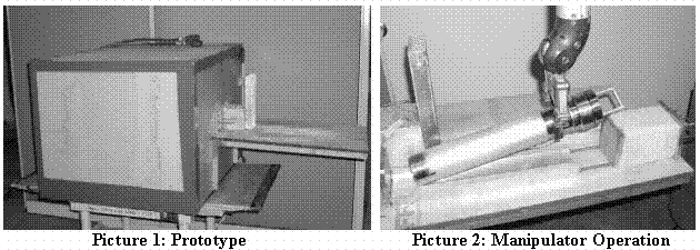
While the final design will have bail for crane installation of the calorimeter system and a stainless steel exterior, the prototype was fabricated with polycarbonate sheets. Picture 1 shows the prototype system and Picture 2 shows the manipulator grasping the container.

Testing
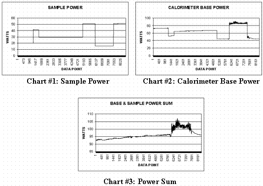
The calorimeter system was initially characterized to develop the reference side correlation and appropriate control algorithm. For sample simulation, an electrical heater was fabricated. Basepower was set to approximately 90 watts for measurement of the maximum container heat load. After initial characterization and testing indoors, the system was moved outside, exposed to all elements and tested. Chart #1 below shows the sample power and how it was varied throughout the testing. Chart #2 shows the calorimeter basepower. Ideally when the sample power and the calorimeter basepower are summed (in the power replacement implementation), the sum will equal a constant value. Chart #3 shows the sample and basepower sum.

It is clear from the data that the system was not stable. Initial thoughts on the power drift were that in due time the power sum would level off. The noisy section of the data, approximately data points 6000 – 8000, were believed to be the result of air in-leakage during a windy timeframe. However, the calorimeter system was dismantled to determine if another cause existed. The solder (low temp solder < 100 C) mounting the thermoelectric cooler wires was found to have melted in several locations indicating too high of an internal temperature.
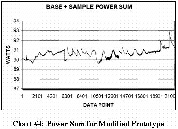
Minor fixes were made to the prototype unit and it was tested again. Chart #4 shows the power sum data. The chart represents 10, 50 watt samples measured over a three week period. Visual interpretation of the data shows a spread of approximately +/- 1.75 watts. Considering a nominal loading of 50 watts, 1.75 watts is below the 5 %RSD goal.

Final Design
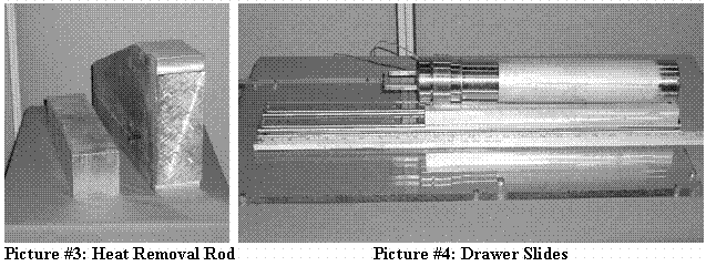
Several changes were incorporated into the final design. First, the heat removal rod was doubled in cross sectional size and will be mated with an aluminum front panel for a reduction in internal operating temperature (Picture #3). Second, wiring within the calorimeter will be changed to utilize PEEK insulated wires for radiation resistance. Third, the sample drawer concept has been modified to mount the drawer on stainless steel slides for easier operation. Picture #4 shows the slide concept with a carrier for the container. These changes have been incorporated into the final design and fabrication work is starting.

Summary
The requirements for operation of this calorimeter are less than ideal. Fortunately, due to its low material category the precision requirements are relaxed and the prototype demonstrated the ability to meet these requirements. The basic design concept incorporated all requirements and is fully redundant without any active components. Problems identified during the prototype stage have been incorporated into the final design. Fabrication and testing is expected to be complete late in 2000.
Reference