Miniature Mass Spectrometers for Hydrogen Isotopic Analyses
W. A. Spencer and L. L. Tovo
Westinghouse Savannah River Company
Aiken, SC 29808
List of Acronyms
|
ADS |
Analytical Development Section |
|
DOE |
Department of Energy |
|
JPL |
Jet Propulsion Laboratory |
|
NASA |
National Aeronautics and Space Administration |
|
NOAA |
National Oceanic and Atmospheric Administration |
|
PDRD |
Plant Directed Research and Development |
|
RGA |
Residual Gas Analyzer |
|
SRTC |
Savannah River Technology Center |
|
SRS |
Savannah River Site, Aiken, SC |
|
TCAP |
Thermal Cycling Absorption Process |
Keywords: Residual Gas Analysis, Mass Spectrometer
Abstract - Summary
As part of the Defense Programs Plant Directed Research and Development Program, the Savannah River Technology Center investigated the emerging area of miniature mass sensors for hydrogen and hydrogen isotope analysis. New sensors from Ferran Scientific and a beta prototype sensor from Mass Sensors, Inc. were purchased. A small pumping platform was designed and assembled. Components for miniature ion traps were investigated based on design information from Oak Ridge National Laboratories. The systems were compared to a conventional residual gas analyzer based on a Stanford Research RGA 300. Each of the sensors investigated had distinct advantages for particular applications. The Ferran system was the least expensive and the smallest, but it had low resolution for hydrogen and deuterium mixtures. The Mass Sensor unit used a new ExB design which achieved excellent resolution of the hydrogen isotopes in a small package. One limitation with the current design was the small 3 to 4 order dynamic range and another was a need for a variable sampling rate to speed analysis over a wider mass range.
1.0 Introduction
Measurement of hydrogen isotopes and other gas-phase analytes in the Tritium Facilities at SRS and in the DOE complex ensure safety and control of operations. Measurements determine the real time partitioning of hydrogen isotopes in the separation processes. Areas of application include hydride bed storage, thermal cycling absorption process (TCAP) operations, gas mixing, and reservoir surveillance. Mass spectroscopy is the preferred method for such measurements.
Large high-resolution magnetic sector mass spectrometers and smaller residual gas mass analyzers are the main instrumentation employed. On-line/at-line miniature mass spectrometry systems would have advantages over these instruments. A miniature spectrometer would take minimal space in a facility where containment space is at a premium. It could cost effectively accommodate multiple process measurements and provide real time process monitoring. In-situ instruments would alleviate the sample load on the laboratory high resolution mass spectrometers.
The requirements for the mass spectroscopy instrumentation were well documented in Philippe Chastagners 1984 report1 , which describes the specification, procurement, and evaluation of hydrogen gas mass spectrometers for the DOE complex. Table 1 lists some of the isotopes of interest and their mass to charge ratio. Note that several isotopes have the same mass number.
Table 1. Hydrogen Isotopes
Table 2 lists the resolution required for separation of key ion pairs by mass spectrometry. In practice, helium-3 can not be separated from tritium but the latter emits beta radiation and can be separated from non-reactive helium using other methods.
Table 2. Resolution of Ion Pairs
Chastagners report describes the development and procurement of large high-resolution, magnetic-sector, gas-mass spectrometers, which were built by Varian and VG to DOE specifications. Today, those instruments are still state-of-the-art in terms of performance, stability, and dynamic range. However, the associated electronics, pumping, valves, and software systems are dated. The systems require considerable space making them impractical for direct process measurements. In addition, the vendor has stopped production of these instruments and support for existing instruments will be minimal over the next 10 years2.
Evaluating alternate and emerging technologies for hydrogen isotope analysis was part of a long-range plan developed to ensure that analytical capabilities in the Tritium Facilities were maintained in the future2. Therefore, SRS used some of its Plant Directed Research and Development funding (PDRD) to support an exploratory investigation into the emerging miniature mass spectrometer technology. This report covers that initial investigation.
Researchers at both NASA and NOAA desire miniature mass spectrometers for space exploration and for deep ocean probes3. Key requirements for their applications are low power, small size, and lightweight, which make remote deployment feasible. Their needs have driven recent developments. Badman and Cooks published a review of the current technology4. Henry has given an overview of the emerging technology5.
Several of the developments have involved miniature ion traps. Cooks group at Purdue lead development of miniature ion traps using simple cylindrical designs6. Whittens group at ORNL extended the work to "bee" sized 1 mm traps7,8. Orient and Chutjian at NASA Jet Propulsion Laboratories demonstrated how ion traps could be used for high-resolution hydrogen gas analyses by shifting the fundamental applied frequency to higher values9. All three found that an advantage of an ion trap was increased sensitivity compared to magnetic and time of flight (TOF) mass spectrometers. However the dynamic range is limited by the trap capacity.
Independent of the ion trap development, Jorge Diaz working in Gentrys group at the University of Minnesota sought to improve and miniaturize conventional double focusing mass spectrometers10. Instead of using a sequence of large electro-magnetic and electrostatic sectors, Diaz overlaid the electrostatic field over a small permanent magnet with a cut flight path to make what is described as an ExB crossed magnetic electrostatic spectrometer. The unit was compact. The electronics were simple. The ion source was a continuous rather than pulsed source. Only a DC stepped voltage was required to shift the mass to charge focus. Unlike quadrupole and ion trap spectrometers, which have the same (typically unit) resolution at all masses, the magnetic design has an absolute resolving power, which makes the separation at low masses very good in comparison. The separation of higher masses was limited. For example, if the system resolving power was 40 then argon measured at mass 40 had a mean unit resolution but hydrogen at mass 2 resolved in 0.05 atomic mass units. The University of Minnesota licensed the technology to Mass Sensors, St. Louis, Mo., for commercialization.
Miniature quadrupoles are being developed. Freidhoff et al. at Northrop Grumman described a micro-machined quadrupole that was etched into a chip substrate. They described a micro scale Wien mass filter11. Ferran and his coworkers at Ferran Scientific have fabricated and built a low resolution 4x4 micro quadrupole mass sensor that provides close to unit resolution and functions as an enhanced ion gauge12.
In addition to the development of the mass sensor, equipment manufacturers have likewise improved pumps, valving, and electronics packaging. Alcatel, Varian, and Pfeiffer have introduced small high efficiency turbo pumps with molecular drag booster stages that enhance pumping of hydrogen13, 14. Air Squared has introduced a new scroll pump that can be used for miniature lightweight oil free backing pump applications15. Oil free diaphragm pumps such as those made by Vacuubrand are already replacing older oil based roughing pumps used in many of the original designs16. Swagelok has introduced a new integrated gas component system, called IGC II, which provides compact modular gas valving for efficient manifold construction17. All of this new equipment facilitates the miniaturization effort.
1.1 Objectives
The goal of the work was to develop a miniature, high-speed mass spectrometer system that will provide accurate and reliable on-line/at-line measurements of gas phase analytes in processes at SRS tritium facilities and in the DOE complex.
1.2 Objective/Scope/Results Expected to be Achieved
A working prototype mass spectrometer would be built and demonstrated. Small pumping systems and integrated modular valves would be evaluated as well as new modular electronic components.
1.3 Conduct of Testing
This work was part of the Defense Programs Plant Research and Development Program. The work was scoping in nature and involved exploratory research of new technologies. The work followed the SRTC research guidelines for exploratory activities and used a technical notebook as the primary means of documentation.
1.4 Results and Perforamce Against Objectives
Three prototype miniature mass spectrometer systems were assembled during the course of these studies. Two small quadrupole mass spectrometers were placed into research support roles within SRTC.
New miniature mass spectrometer technologies were identified including a small cross magnetic-electrostatic field sensor that had high resolution for hydrogen isotopes. A miniature cylindrical ion trap was built but needs further development especially for low masses.
Small turbo pumps from Pfeiffer, Alcatel, and Varian were found to be effective for analytical mass sensor application. Modular valve systems were demonstrated to be effective if properly assembled. Modular electronics enabled remote monitoring across the internet using TCP/IP protocols.
1.5 Quality Requirements
This work was done as an exploratory scoping activity to investigate possible use of emerging technologies applied to SRS processes. The primary QA requirements are defined in the WSRC 1Q manual Section 2-3 covering Conduct of Research and Development Activities. The main QA requirement from that procedure was to document studies in the researchers notebook. In addition, work was done according to guidance in WSRC-IM-97-00024, rev. 2, Savannah River Technology - Conduct of Research and Development Manual.
2.0 Instrumentational Approach
The following equipment and instrumental set ups were used in the experimental studies of this project.
A basic residual gas analyzer (RGA) was used for comparison with experimental designs. The reference RGA had a Model 203 Granville-Phillips variable leak for an inlet. The leak was connected to a small 4" vacuum chamber using a 2 ¾" CF flange adapter. A Stanford Research RGA 300 quadrupole with electron impact ionization source monitored the chamber. A Pfeiffer TMU 260 Turbo pump with a Vacuubrand MD4 membrane backing pump pumped the chamber. Residual background pressure was around 1x10⁻⁹ Torr after a bake out. Normal operating pressure was adjusted by opening the leak to 4x10⁻⁶ Torr for optimum running conditions. Pressure was measured with a Pfeiffer full range Pirani/Cold Cathode Gauge, Model PKR 251 with gauge display. The control head from the RGA communicated via a serial port to a personal computer. One modification to this system was to add a 10 port Swagelok IGC II modular inlet manifold in front of the variable leak to allow switching of the inlet source. A second modification was to write external code using Microsoft Visual Basic with National Instruments Component Works calling to Stanford Research dlls to allow direct interfacing of custom operations with a process.
The experimental designs were all mounted on a common platform, which used an Alcatel ATH30+ turbo pump with dual stage molecular drag. The pump was approximately one third the size of the standard Pfeiffer TMU 260 and had a 2 ¾" CF flange connected to a 5 way 2 ¾" CF tee. A Granville-Phillip variable leak was used for an inlet and a Pfeiffer Pirani/Cold Cathode to monitor vacuum pressure. A Vacuubrand MD1 membrane pump was connected as the backing pump. One port of the tee was covered with a BK7 view port if not needed for a mass analyzer connection.
Three small mass analyzers were connected to the experimental platform. These included a 0-45 mass range miniature hexadecimal pole [4x4] all glass/ceramic analyzer made by Ferran Scientific, San Diego, CA. This system used a small 1 inch cube preamp and a modular Symphony embedded controller box before connecting to a personal computer via a serial line.
A second system was made by Mass Sensors, St. Louis, Mo., using a cross magnetic electrostatic field. This was a beta prototype system of their initial product offering. The analyzer was mounted on a Kwik connect KF-50 flange and adapted down to the CF 2 ¾" vacuum system. The analyzer had a small 2"x5"x7" control module that provided the power for the electron ionization source and provided a sweep voltage for the electrostatic field. The unit provided high voltage to the electron multiplier. Output from the detector went to small 1 inch in-line preamplifier that was located about 6 inches from the analyzer head. Output was sent to an ADC converter and moved to a second 1"x4"x3" communications controller module. The communications module provided an Ethernet connection running TCP/IP protocols. The mass unit could be accessed by any computer inside of the firewall that had the appropriate passwords and communication software for requesting a mass scan.
The third system was our attempt to duplicate and improve upon an Oak Ridge micro scale cylindrical ion trap. The basic trap was very close in design to those described by Whitten et al. at ORNL and by Graham Cooks's group at Purdue. Our trap had a rhenium wire filament, a gate electrode, an entrance cap electrode with a 1-mm inlet hole, a ring electrode with a 2.5-mm internal diameter, and an end cap with a 1-mm hole. The distance between the two end caps was 5.4 mm. We mounted a high temperature Amptek electron multiplier to the back of the exit hole. The detector connected to an Amptektron MD-502 preamplifier pulse discriminator. Output digital pulses were then sent to an EG&G ORTEC MCS PCI multichannel scalar card mounted inside of the personal computer running Windows 2000. Frequency waveforms were generated using a Stanford Research DS 345 30 MHz synthesized function generator. This fed a Henry Electronics [RadioDan Electronics] Model 100B-27 booster amplifier. The booster had a 2 to 27 MHz range and utilized two modular brick amplifier stages. The first stage provided high gain with a nominal drive of 1 milliwatt input and 10 watt output. The second stage was mainly a current amplifier boosting power from 10 watts to 100 watts. The second stage was usually by passed in our experiments. A MFJ Model 969 Deluxe Versa Tuner II was used to provide a matching network between the amplifier and the trap. A MFJ-872 PeakReading SWR/Wattmeter was used to track the RF output. Detector signals were also monitored with a Tektronix TDS 224 100 MHz digital 4 channel oscilloscope and with a Keithley Model 617 electrometer. Ionization pulses were provided with a Hewlett Packard Model 214B pulse generator. The pulse generator, the frequency synthesizer, and the scope were easily triggered by an external signal from the multichannel scalar card to synch the sweep voltage with the scalar channel position.
3.0 Results and Discussion
Figure 1 shows a series of samples taken with the Stanford Research RGA 300 quadrupole during a study of off gases from radiolysis. We used this system as our reference system. Note that each of the peaks is approximately the same width. We found this system had excellent dynamic range and stability. The background pressure and electronic preamplifier gains were easily adjusted to cover over 7 orders of detection range. The ionization filaments have lasted over 2 years. The system was easily programmed from Visual C++ and Visual Basic for integration with experimental valving. LabView drivers were available.
To test the systems, a mixture of hydrogen and deuterium was used. The mixture had masses at 2, 3, and 4. Figure 2 shows the separation obtained with the Ferran miniature hexadecimal pole sensor. Masses 2 and 4 were easily separated but as shown in Figure 3 the resolution for the small mass 3 peak was poor. The Ferran system had other disadvantages that should be easily fixed by the manufacturer. The graphical software was difficult to use with multiple windows and multiple file storage. The graphics modes did not autoscale and the data view range was limited to pre-programmed choices. Filament on/off controls were on a different window then the data collection and display window which made set up somewhat confusing. Figures 4 and 5 show the sensor, preamplifier, and electronic module for the Ferran unit. As can be seen from the photos the sensor and electronic packages are small. A serial line connects the detector to a personal computer for control and display.
Figure 6 shows analysis of the same hydrogen and deuterium mixture using a beta prototype of the Mass Sensors ExB design. The resolving power of this sensor is about 40 and as mentioned above, resolution is constant at all masses. The spectrum shows the hydrogen, deuterium, water, nitrogen, and air peaks. The small HD peak at mass 3 was easily resolved. Figure 7 shows a scan with hydrogen, nitrogen, and argon. Note the apparent increase in the peak width at the higher masses. In this sample, hydrogen was only 2 percent of the total but had a peak height larger than the 49 percent argon signal. Peak area was more proportional to the true concentration. Figure 8 shows a scan from mass 1 to 7 with the Mass Sensor unit.
The Mass Sensor design was a beta prototype and had several limitations because it was a new product. The primary concern was that the dynamic range of the system was limited to about 2000. This appeared to be mainly due to the noise level and drift of the low level background current of the detector. The shielding of the sensor wiring needs improvement. The test unit was hand wired. When we redirected the detector output to a Keithley 617 electrometer, we were able to decrease the noise levels by about a factor of 10. However that electrometer forced us to slow the scan rate to several minutes. It appeared to us that high frequency noise was leaking into the system.
In the prototype operating system, the sampling frequency was fixed to a constant mass step. Very narrow hydrogen peaks needed to be sampled with better than 0.01 mass unit steps. This made scanning of the argon peak tedious as 0.2 mass unit steps would have been adequate. Mass Sensors is working on a logarithmic sampling algorithm that should resolve the problem decreasing the total scan time and maintaining constant resolution. The code was a windows style interface and easy to use. One problem was in the area of fail safe modes. An overnight power failure managed to latch off the pump systems but left the filament current running and therefore, the filament burnt up. Fortunately a second ionization filament had been provided.
A unique feature of the Mass Sensors system was that it came with a direct TCP/IP interface connection rather than a direct serial line. We demonstrated that a USB to Ethernet converter could be used to convert the system back to a direct connection if the network interfaced needed to be avoided for security reasons. With a TCP/IP connection, the system could be operated from any computer inside the site firewall. The software was able to rapidly search the network for devices and provide a list of sensors.
A basic advantage of the Mass Sensor ExB design was its fundamental electronic simplicity. The electron impact ionization source was a filament with a DC off set that provided a constant ion current. Timing gates were not needed. The magnetic field was fixed. A DAC voltage stepped by the small embedded controller was sent to a high voltage operational amplifier. This provided the static potential for sweeping the electrostatic field. Holding the voltage at a fixed value allowed integration at a single mass and peak jumping was possible. Because the electronics required only low current voltage converters, a few operational amplifiers, and connectors, the entire electronic package for the spectrometer was about the size of a small hard cover book.
In addition to the above two spectrometers, we attempted to build a small ion trap spectrometer. The design was based on a small 1 mm "bee" size trap that Bill Whittens group at ORNL had reported. ORNL showed us their unit and demonstrated its use with a helium background. Xenon isotopes were nicely separated. We increased the size from 1 mm to 2.5 mm mainly to increase the size of the trap capacity. Otherwise the physical layout matched closely the ORNL one. Figure 9 shows a schematic of the trap design. Figure 10 shows the experimental platform that was used to test the trap. Components were built from standard 2 ¾" ConFlat tees. An Alcatel ATH30+ miniature turbo pump with molecular drag secondary stages provided the main vacuum. The ion trap was mounted to electrical feedthrough flanges located on one of the tee flanges. This same platform was later used for the Ferran and Mass Sensor units. Figure 11 shows the Granville-Phillips leak with a 25-cc sample reservoir attached. Instead of an analog detector, we used the electron multiplier in the pulse counting mode. The detector for the trap was an Amptek high temperature electron multiplier with a pulse pre-amplifier/ discriminator module connected via a short coaxial cable. Another coaxial cable connected the output from the discriminator to an ORTEC multichannel scalar card that was installed inside a personal computer. A start pulse and a delayed DAC sweep provided the signal for pulsing the ion source and for ramping the RF amplitude from the signal generator. The signals were accumulated in 64,000 channels on the multichannel card. Channels bins were programmable and usually reduced by software to 8000 channels. The sweep rate and the multichannel bins were software programmable. A minimum time per channel was 10 nanoseconds due to the pulse length of the detector output. Normally the dwell time in each bin was 2 milliseconds. Multiple sweeps could be combined to increase the total capacity of the bins. The system with controlled signals worked well based on scans with an oscilloscope.
However, with real detector input we had several problems with our ion trap system. Most of the problems appear to be due to our choice in the electronic configuration. RF signal was readily picked up by the detector. In addition the ionization pulse was too weak.
RF pulses were counted as they leaked into the detector. As the RF voltage amplitude increased more signal leaked. At high leakage or counting overloads, the preamplifier was confused. A negative bias developed in the output signal from the pre-amplifier. The bias showed as a shifted signal pulse. Instead of being from 0-5V, it moved down to -5 to 0 V. The pulse discriminator would stop counting the detector pulses once the voltage of the pulse dropped below the discriminator setting, which was usually set to count only pulses above a threshold of 1.5 V. This might have been from over powering the trap with too much RF or from poor shielding choices for the RF. Figure 12 shows a photo of the trap with the detector. The detector pulse problem was somewhat frequency dependent occurring more easily at the higher frequencies, especially when above 8 MHz. All of the cables were less than two meters. Inside connections were less than 4 inches and the RF was shielded as much as possible. One observation was that the RF matching network clearly tuned easier at some frequencies than others based on the SWR signal to the trap. A trap well tuned with the matching network took little power to saturate the detector. RF breakdown levels in ion traps have not been discussed well in the literature.
Another problem with our ion trap was the ionization source. Ideally the ion source will provide a high concentration of electrons to the trap when pulsed. The electrons will be accelerated into the trap and ionize the gases in the trap chamber which are then separated by an increasing RF field. Our ion source was not efficient and we had not tried to align an electron beam into the trap entrance hole. The maximum voltage of the source was set to less than 50 V, because this voltage limit enabled work in our laboratories with a single person. Our safety rules require two man coverage to work with higher voltages. The Oak Ridge design as well as almost all commercial ionization systems require voltage off sets between 70 and 300 V. At this stage we do not see a way to avoid using higher voltage potentials to move electrons from the ionization filament into the trap.
Although our trap design was not successful this area of research was being successfully pursued by others. Graham Cooks group at Purdue published a detailed description of one of their traps in two featured articles in Analytical Chemistry in December 20026. A trap design was published on the magazine cover. A. Chutjians group at JPL modified a commercial Finnegan trap by changing the applied RF frequency and showed that low mass separations could be done and that the helium buffer gases are not always needed9.
One of the benefits of this study was exposure to new technologies. Figures 13 and 14 show the Stanford Research RGA 300 with a Swagelok IGC II manifold. We had a research customer application which required that a multiple port inlet system be built. Because we had researched new emerging technologies as part of this PDRD program, we were able to convince the researcher to use his funds to purchase and evaluate the new modular designs. Our experience with the Swagelok design indicate that it will work as well as the conventional welded manifolds that are used in many of the SRS gas manifold inlet systems provided the units are carefully assembled and torqued to specifications. Swagelok provided a design program for configuring the manifold which was easy to use and enabled custom designs with little effort. The assemblies took only a few minutes to assemble but required some careful tightening of the bolts to assure that all potential leaks were sealed.
Likewise the Ferran Scientific sensor was acquired by another researcher for monitoring diffusion of hydrogen. The system was acquired based on our recommendations. Since the application only required low resolution, this inexpensive mass sensor was an ideal choice and resulted in considerable savings compared to full higher resolution quadrupole system.
4.0 Conclusions, Recommendations, and Future Work
Our studies indicate that miniature mass spectrometers are being successfully developed and can be used in selected applications.
- Conventional quadrupoles should continue to be used in applications where unit resolution and long term stability are required. However, the smaller backing pumps and turbo-pumps available commercially should be used with these conventional quadrupoles to make small compact analyzers.
- Developments in miniature quadrupoles and ExB mass analyzers should be monitored as rapid improvements in the technology are likely.
Miniature quadrupoles appear to be limited to near unit resolution in the present configuration. A breakthrough such as operating at higher frequencies on the filters or improvements in micro machining of rods to improve absolute linearity will be required to greatly enhance performance. Quadrupole systems are the least expensive mass analyzers available and provide stable performance. Smaller multi-pole systems such as that used in the Ferran system will find useful niche applications in intelligent gauge applications.
The ExB mass sensors have an advantage in cases where clear separations of low masses are needed. A slightly larger ExB design might provide a compact mass spectrometer with performance comparable to the larger dual sector mass spectrometers. The miniature design that is currently available is still in the prototyping stage and the spectrometer needs improvements in both its dynamic range and in general use software before being readily useful in a plant application.
- Development work to make trap technologies available for low mass separations should continue.
- Ion traps and the related Fourier Transform-Ion Cyclotron Resonance systems have the potential of providing very high resolution and improved sensitivity over other methods. Traps enable fundamental studies of ion reactions because ions can be separated and reused in them. This could be critical to our understanding of hydrogen processes. However, these systems have usually been optimized with a residual back pressure made by addition of helium which is undesirable for hydrogen isotopic measurements. Low masses have rarely been studied with traps because of the high background. Traps are unlikely to have the dynamic range provided by the magnetic and linear quadrupole mass spectrometers and will not have a linear response. That is, quantization will be less accurate than magnetic systems. Our failure to duplicate promising experiments at ORNL and JPL were mainly due our inexperience with building mass spectrometers and their ion sources from scratch. We would expect more success over time. We feel that this technology should not be dropped as a potential research approach to improved mass analyzers.
- The site should acquire a time-of-flight mass spectrometer system to gain expertise with the technology. Time-of-flight mass spectrometers are increasingly available and have been successfully used for large masses. We chose not to investigate them within the scope of this project, but development of these systems and their use for measuring the lighter masses should be investigated.
References
- P. Chastaner, "Advanced mass spectrometers for hydrogen isotope analyses", NASA Technical Reports, Document ID 19850006841 N(85N15150), Report Number DE85-000716, DP-1674, 90p, (Jun 01, 1984). [ Available in pdf format from http://kratos.osti.gov ]
- C. M. Gregory, C. B. Mauldin, "Proposal to Purchase Spare Finnigan MAT 271 Mass Spectrometer and $600,000 Spare Parts (U), TSD-APS-2001-00013, (May 1, 2001).
- The 3rd Harsh-Environment Mass Spectrometry Workshop and The 2nd NASA/JPL Miniature Vacuum Pumps Workshop, March 25-28, 2002, Pasadena, CA
- Ethan R. Badman and R. Graham Cooks, "Miniature Mass Analyzers", J. Mass. Spectrum. 35, p 659-671 (2000).
- Celia M. Henry, "The Incredible Shrinking Mass Spectrometers", Analytical Chemistry 71, p264A-268A, (April 1, 1999).
- Garth E. Patterson, Andrew J. Guymon, Leah S. Riter, Mike Everly, Jens Griep-Raming, Brian C. Laughlin, Zheng Ouyang, and R. Graham Cooks, "Miniature Cylindrical Ion Trap Mass Spectrometer, Analytical Chemistry, 74, p6145-6153, (December 15, 2002).
- O. Korienko, P.T. Reilly, W.B. Whitten, J.M. Ramsey, "Electron Impact Ionization in a Micro Ion Trap Mass Spectrometer", Review of Scientific Instruments 70, pp3907-3909, (Nov. 16, 1999).
- Oleg Korienko, Peter T.A. Reilly, William B. Whitten, and J. Michael Ramsey, "Field-Emission Cold-Cathode EI Source for a Microscale Ion Trap Mass Spectrometer", Anal. Chem. 72, pp559-562, (2000).
- O.J. Orient and A. Chutjian, "A Compact, High-Resolution Paul Ion Trap Mass Spectrometer with Electron-Impact Ionization", Review of Scientific Instruments 73, pp2157-2180, (May 2002).
- Jorge A. Diaz, Clayton F. Giese, and W. Ronald Gentry, "Portable Double-Focusing Mass-Spectrometer System for Field Gas Monitoring", Field Analytical Chemistry and Technology, 5(3), pp. 156-167, (2001).
- C.B. Freidhoff, R.M. Young, S. Siram,T.T. Braggins, T.W. OKeefe, J.D. Adams, H.C. Nathanson, R.R.A. Syms, T.J. Tate, M.M. Ahmad, S. Taylor, and J.Tunstall, "Chemical Sensing Using Nonoptical Microelectromechnanical Systems", J. Vac. Sci. Technol. A 17(4), pp 2300-2307 (Jul/Aug 1999).
- Ferran Scientific, San Diego, CA, www.ferran.com
- Alcatel, see, www.lacotech.com/products/ATH31.pdf
- Pfeiffer, http://www.pfeiffer-vacuum.de/web/index1.php3?lang=e
- Air Squared, www.airsquared.com
- Vacuubrand, http://www.vacuubrand.de/com/index.html
- Swagelok, www.swagelok.com/downloads/webcatalogs/MS-02-134.pdf.
Acknowledgment
The authors wish to thank William Whitten and Jeremy Moxom of Oak Ridge National Laboratories for reviewing with us their ion trap designs and for showing us their laboratories. The authors want to thank Phil Berger, Rajiv Chhatwal, and Henry Rohrs of Mass Sensors, Inc., for detailed assistance with the ExB mass sensor.
The authors wish to thank Paul S. Korinko for procuring and lending to us the Ferran Scientific mass sensor system and Donald L. Fisher for lending the Swagelok IGC II inlet port. We want to thank Donald J. Pak and Jerry McCarty for assistance with mechanical designs and equipment packaging.
Figure 1. The SRS RGA 300 residual gas analyzer was used
as a reference system.
Shown are scans from a radiolysis offgas study. Samples had
water, air, argon, and traces of hydrogen and ethanol.
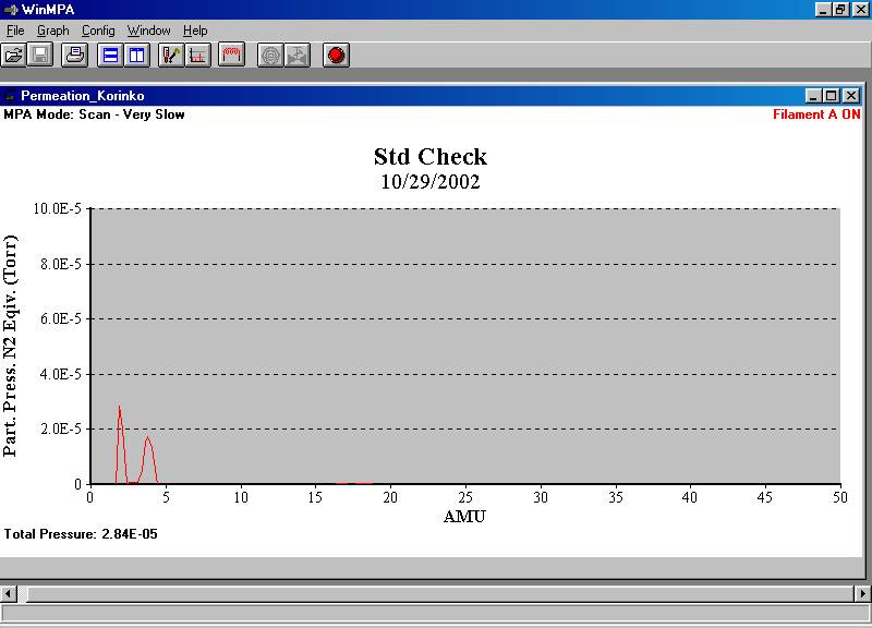
Figure 2. Hydrogen and deuterium separation using a 16 pole Ferran sensor.
Figure 3. Ferran sensor can barely resolve mass 3 from masses 2 and 4.
Figure 4. The pre-amplifier of the Ferran
Scientific system attached to a
small embedded controller module that provided a
RS232 interface to the display computer.
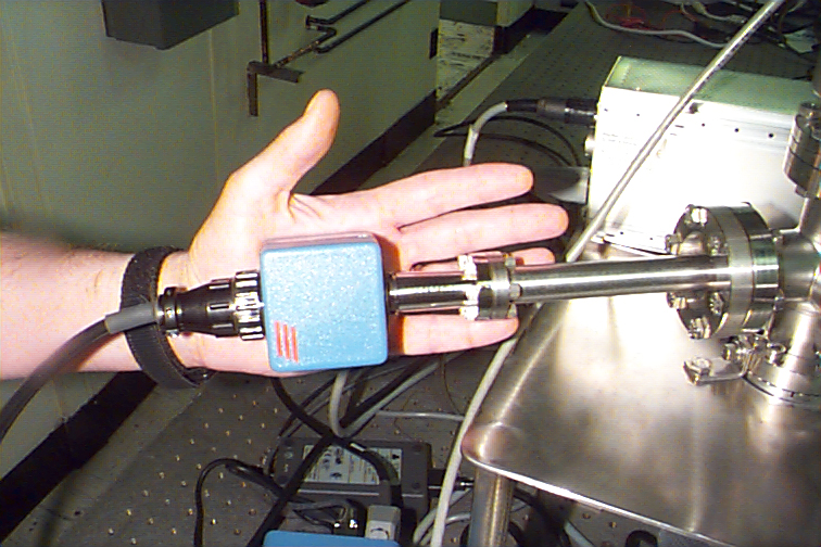
Figure 5. Ferran 16 pole sensor with pre-amplifier is smaller than a hand.
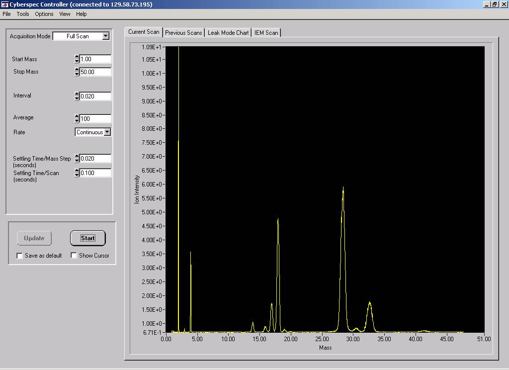
Figure 6. Mass Sensors ExB sensor has
good resolution for hydrogen and deuterium
but only unit resolution for nitrogen-28 and oxygen-32. The system
has a small electronics foot print and uses an Ethernet IP address
to communicate. The spectrum can be viewed remotely.
Figure 7. Mass Sensors ExB scan for mixture of hydrogen, nitrogen, and argon.
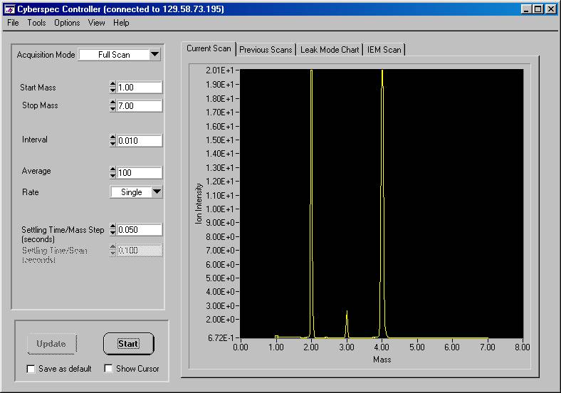
Figure 8. Enhanced scan from mass 1
to 7 for a hydrogen and deuterium
mixture using a Mass Sensors ExB unit. System
pressure was 3x10⁻⁵ Torr and the hydrogen
peak is saturated at an ion intensity
of 20. A lower limit ion intensity
was 0.68±0.01.
Figure 9. Schematic of a miniature ion trap based on ORNL design.
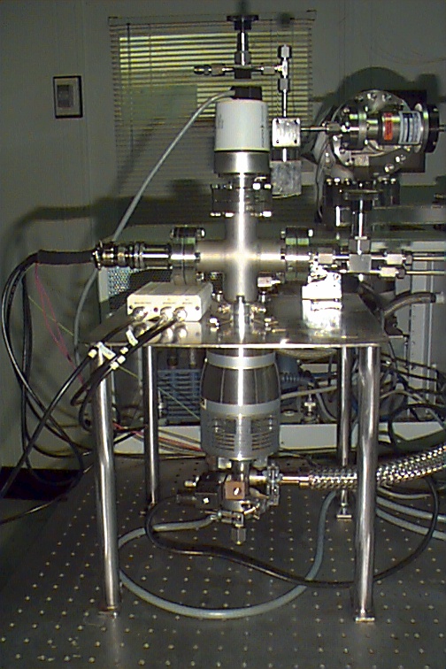
Figure 10. Experimental test setup included
a Granville-Phillips variable
leak, a Pfeiffer combination Pirani/Cold Cathode
gauge, an Alcatel ATH30+ turbo pump with
molecular drag for enhanced hydrogen
pumping with a VacuuBrand
diaphragm backing pump.
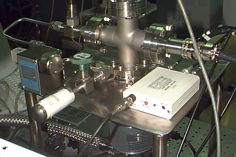
Figure 11. Close-up of an attached sample
and the miniature ion trap
with Amptek pulse counting detector. An ORTEC
multichannel scalar card was used to count pulses.
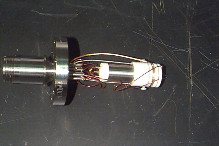
Figure 12. Close-up view of the miniature
ion trap with Amptek
electron multiplier detector. RF leakage
across wiring was a problem in this design.
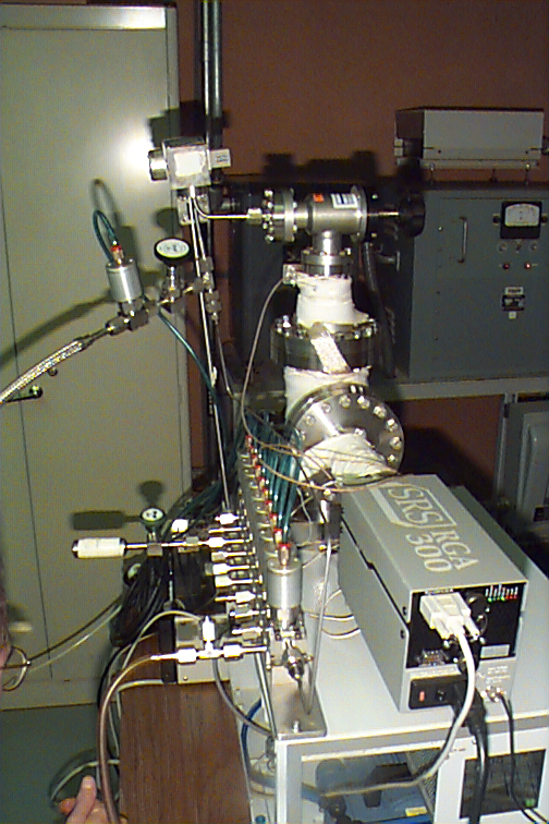
Figure 13. Comparison system was a SRS
RGA 300 quadrupole used
for general residual gas analyses in the laboratory.
Shown with the unit is a new modular valve assembly from
Swagelok that was used a an inlet switching system.
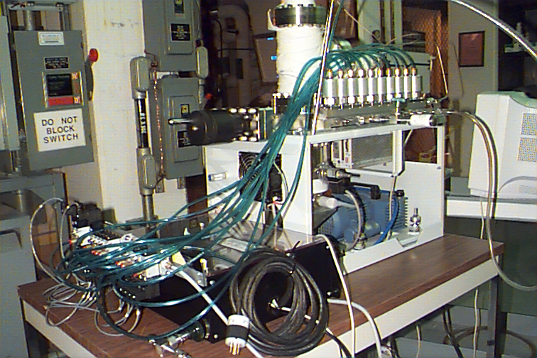
Figure 14. Inlet manifold was driven
pneumatically. A National
Instruments Field Point interface with pneumatic
relay valve manifold interfaced to the
inlet and a computer system.