Figure 3.1 – DWPF Melt Cell - End View
WSRC-TR-2001-00248
Conceptual Methods for Decontamination and Decommissioning,
Size Reduction,
and Disposal of the DWPF Melter and Components
Michael E. Smith, Dennis F. Bickford, and Frank M. Heckendorn
Westinghouse Savannah River Company
Aiken, SC 29808
This report was prepared as an account of work sponsored by an agency of the United States Government. Neither the United States Government nor any agency thereof, nor any of their employees, makes any warranty, express or implied, or assumes any legal liability or responsibility for the accuracy, completeness, or usefulness of any information, apparatus, product or process disclosed, or represents that its use would not infringe privately owned rights. Reference herein to any specific commercial product, process or service by trade name, trademark, manufacturer, or otherwise does not necessarily constitute or imply its endorsement, recommendation, or favoring by the United States Government or any agency thereof. The views and opinions of authors expressed herein do not necessarily state or reflect those of the United States Government or any agency thereof.
This report has been reproduced directly from the best available copy.
Available for sale to the public, in paper, from: U.S. Department of Commerce, National Technical Information Service, 5285 Port Royal Road, Springfield, VA 22161, phone: (800) 553-6847, fax: (703) 605-6900, email: orders@ntis.fedworld.gov online ordering: http://www.ntis.gov/support/ordering.htm
Available electronically at http://www.osti.gov/bridge/
Available for a processing fee to U.S. Department of Energy and its contractors, in paper, from: U.S. Department of Energy, Office of Scientific and Technical Information, P.O. Box 62, Oak Ridge, TN 37831-0062, phone: (865 ) 576-8401, fax: (865) 576-5728, email: reports@adonis.osti.gov
1.0 Background
The Defense Waste Processing Facility (DWPF) melter was started up in 1994. Seventy canisters were filled during Waste Qualification runs using non-radioactive feeds. The melter then began processing radioactive feeds in early 1996 and the first canister with radioactive glass was filled on April 27, 1996. Over 34 millions gallons of radioactive waste will be treated. To date over 1000 canisters have been filled with more than four million pounds of radioactive glass. Approximately 1/6 of the projected canisters to be filled by the DWPF has been completed.
During the processing of this high level waste (HLW) at DWPF a need will arise to develop remote and/or robotic systems to disassemble contaminated HLW processing equipment. This includes failed melters, process vessels, and process equipment. The current approach is to store this equipment in Failed Equipment Storage Vaults (FESV). While this storage is acceptable in the short term, technology must be developed to properly dispose of this equipment. This should include dismantling/size reduction of the equipment, decontamination, disposal of the majority of the material as low level waste (LLW), and disposal of the remaining fraction as HLW materials.
At the heart of the DWPF is the melter. The DWPF melter will probably be the most difficult DWPF HLW equipment to disassemble and decontaminate. A single DWPF melter can hold up to 16,000 pounds of HLW glass. It will also contain additional contamination from unmelted waste solids such as volatile cesium and ruthenium.
If an approach can be developed to dismantle and dispose of the melter, then similar techniques could be used with other HLW processing equipment. The design life of the melter was two years. This was based on a cited corrosion rate of the melter Monofrax K-3 refractories of 5.4 mils per day.1 This corrosion rate was proven to be very conservative. The actual expected corrosion rate should be much less and is based on pilot scale melter work and the operating history of the first DWPF melter (Melter 1). This melter is still operating in the DWPF after seven years. Although the melter design has proven robust, the life of future DWPF melters may not be as long due to the processing of feeds with higher levels of noble metals.2
The expected operations time for DWPF is about 25 to 30 years. During this time several melters will most probably fail and be temporarily stored in Failed Equipment Storage Vaults at the DWPF. There is no facility at SRS that can be used to perform the dismantlement work on these melters. One concept would return failed melters and other large equipment to the DWPF Canyon after waste processing at DWPF is completed. The equipment would then be disassembled and size reduced in the canyon. The required manipulators, tools, etc. are not currently in place or specified. In addition, there is no existing plan on the dismantlement of a DWPF Melter. The need to remotely disassemble and size reduce HLW equipment is a DOE complex wide problem. Making the task somewhat more difficult is the fact that the various sites have different melters and different facilities available to do the work.
2.0 Introduction
The DWPF has processed over 4 million pounds of HLW glass since 1996. A milestone in the Federal Facilities Agreement Part C has been negotiated with the South Carolina Department of Health and Environmental Control (SCDHEC), the Environmental Protection Agency (EPA), and DOE-SR to remove and vitrify all of the SRS HLW by the year 2028. DOE has stated a commitment to meet the 2028 date.
The slurry fed ceramic-lined DWPF Melter is the heart of the vitrification process. In addition to the melter, there are several other large process equipment pieces such as tanks, off-gas components, pumps, etc. The DWPF does not have the capability to decontaminate, size-reduce, segregate, classify, and package for disposal the melter and other large, highly contaminated DWPF equipment. There is no facility to process this large equipment at SRS. Several concepts have been proposed. One is to use the DWPF Canyon after all of the HLW has been treated. Another is to modify an exiting facility at the Savannah River Site (SRS). Finally, a new facility could be built to disassemble, size reduce, and decontaminate large equipment from the various SRS areas.
This report identifies potential methods for the disassembly, size reduction, and decontamination of large DWPF equipment. It specifically targets the DWPF Melter. Methods found to work on the melter should be easily applied to other equipment, as the melter is the most complex large-scale equipment that must be processed. It is also likely to be the most contaminated component as it could contain up to 16,000 pounds of HLW glass in it when it is shut down.
This report also evaluates methods, equipment, and techniques that may be used. It also discusses possible dismantlement sequences that could be used as well as issues that need to be addressed. In addition, past experiences in dismantling and inspection of various ceramic-lined melters will be discussed.
This report fulfills the TFA milestone D.2-2 "Issue report on recommended methods for failed equipment processing at DWPF" due June 1, 2001 under technical task plan (TTP) SR16WT31 (WSRC Immobilization).
3.0 DWPF Melt Cell Description
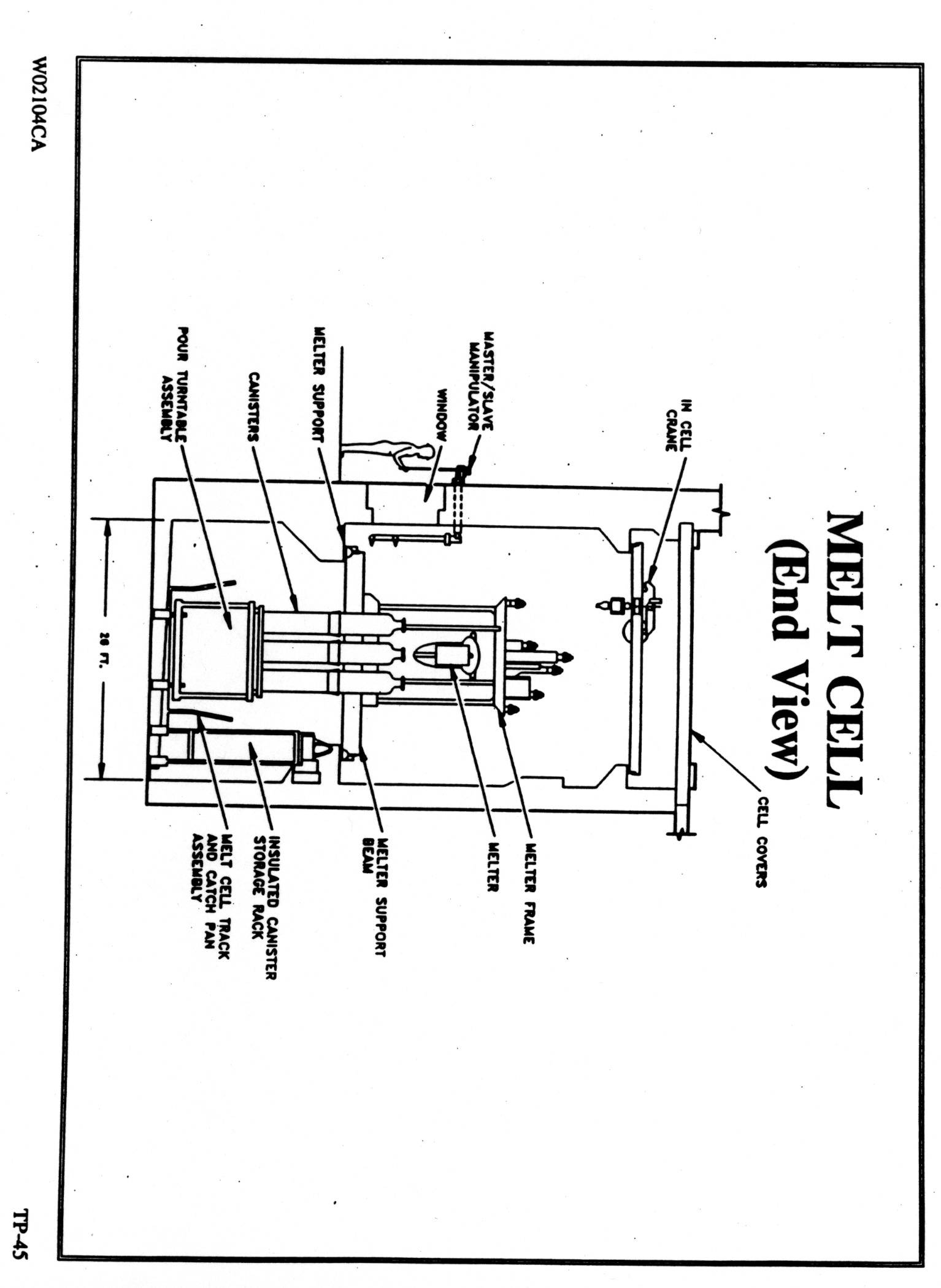
The DWPF Vitrification Building is 360 feet long and 117 feet wide. It is 94 feet high and is an earthquake and tornado resistant concrete structure. The waste processing cells (including the Melt Cell) have 4.5-foot thick concrete walls. The Melt Cell is 73 feet long and 26 feet wide. It is 43 feet high and has 5 windows which personnel can use for various views of the Melt Cell.
The Melt Cell includes the DWPF Melter, the Drain Turntable Assembly, the Pour Turntable Assembly, an insulated Canister Storage Rack (can hold 4 canisters), an Equipment Storage Rack, and the Inner Canister Closure (ICC) Station. Figures 3.1, 3.2, and 3.3 give different schematic views of the Melt Cell.
The Melt Cell has an in-cell crane and removable cell covers. The Melt Cell in-cell crane is a bridge-type crane. It has a steel I-beam frame, called the bridge assembly, that rides on steel wheels and rails for side to side movement as seen from the viewing window. A trolley assembly provides forward and backward movement so the hoists can be positioned almost anywhere in the cell. The in-cell crane main hoist is connected to a canister grapple that can grab canisters. The grapple has a 15,000 pound load capacity. The 1,000 pound auxiliary hoist is operated the same way as the main hoist.
There are also several master-slave manipulators (MSMs) that used to perform various functions in the Melt Cell such as inserting the tapered canister plugs into canisters. These MSMs can be used for light duty repair functions as well, but have limited reach.
In addition to the in-cell crane and the MSMs, the Melt Cell has a modified Par Systems 6350 Tele-Robotic Manipulator (TRM). The main purpose of the TRM is to permit recovery of the melter pour spout when it is plugged with glass. This includes inspection and cleaning of the pour spout, as well as insertion and removal of pour spout inserts. It is also used to perform routine operations such as installing an ICC plug in the throat of a canister. In addition, the TRM can perform the following tasks:
Figure 3.1 – DWPF Melt Cell - End View
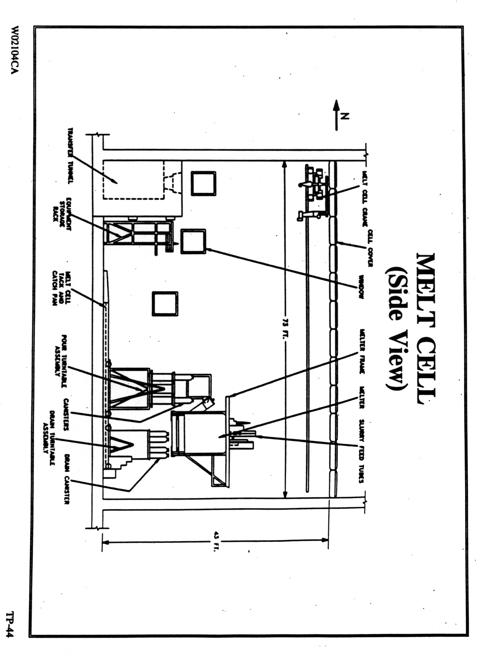
Figure 3.2 – DWPF Melt Cell – Side View
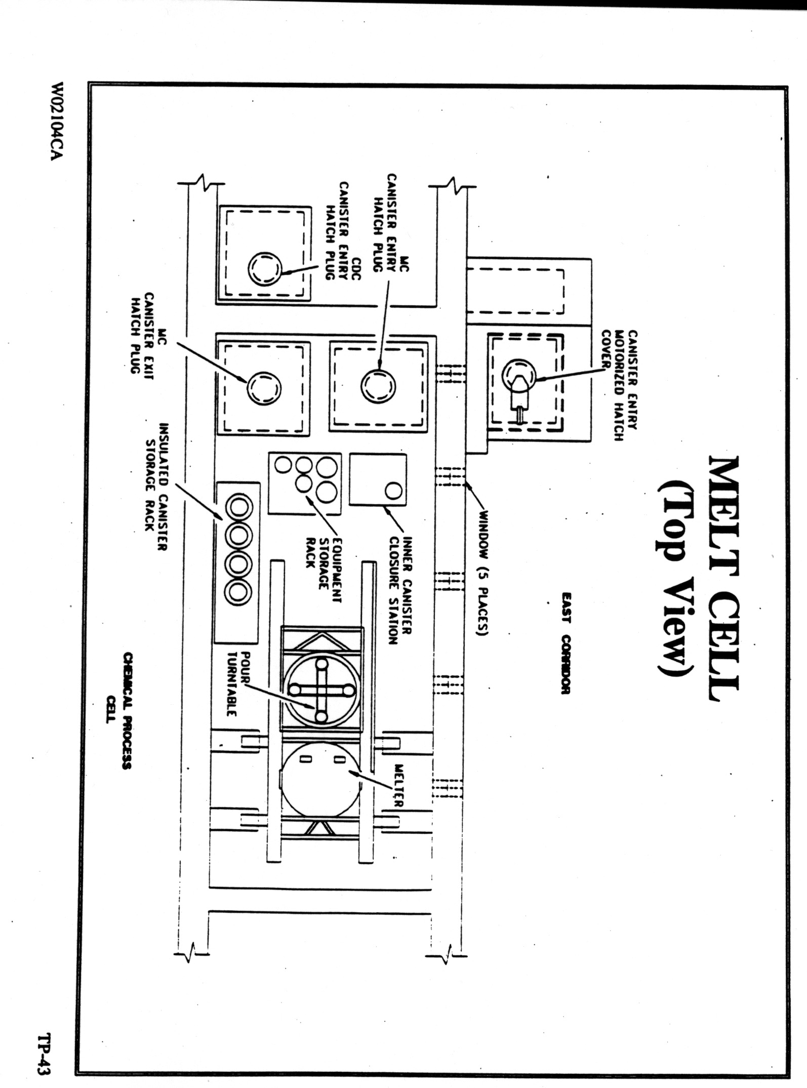
Figure 3.3 – DWPF Melt Cell – Top View
4.0 DWPF Melter Description
The DWPF Melter, shown in Figure 4.1, is a refractory-lined, sealed, stainless steel vessel with a 6 feet internal diameter and approximately 7 feet of internal height. Figure 4.2 shows DWPF Melter 1 assembly with the frame. The 1.5-inch thick vessel shell is SA 240-304L steel with an outer diameter of 8'-4.5" and an inner diameter of 8'-1.5". Inconel 690 is used for the two off-gas nozzles and flanges. The chromium content of Inconel 690 is 27 to 31 percent. To ensure maximum corrosion resistance, a minimum amount of 29 percent chromium was specified for all Inconel 690 used in the melter.
The shell contains no remotely removable parts; all shell components have at least a two-year design life. The melter vessel construction consists of a stainless steel outer vessel (shell) with an inner refractory liner for primary glass containment. The outer shell is water-cooled to maintain the shell at or below 50° C to minimize air updrafts in the Melt Cell.
Primary glass containment is achieved by use of 12-inch thick Monofrax K-3 fused cast refractory brick (product of Monofrax Co.). This refractory is very dense and hard, as it required diamond cutters when cutting the pieces installed in the melter. Korundal XD refractory was used in the vapor space. Zirmul refractory was chosen for the refractory placed underneath the Monofrax K-3 because tests had shown that the reaction of glass with Zirmul creates a very viscous product that helps prevent further glass penetration.
During operation, the glass is maintained in a molten condition by passing a current from the electrodes through the resistive glass pool. As current is introduced into the glass, the resistance of the glass converts the electrical energy into heat. The glass is maintained between 1050 - 1170° C. The DWPF Melter electrodes are four uncooled plates fabricated from Inconel 690 of sufficient thickness to last greater than two years. The corrosion rate of the Inconel 690 in the glass pool is expected to be less than 1.8 mils/day. The electrode stems are water-cooled.
The DWPF Melter vessel shell is penetrated in the vapor space by four pairs of horizontal resistance-type Inconel 690 dome heater tubes. Each tube is three inches in diameter.
The DWPF riser heater consists of an Inconel 690 serpentine heater that surrounds the four-inch inside diameter Inconel 690 riser channel. The pour spout heater also consists of an Inconel 690 serpentine heater that surrounds the two-inch diameter of the pour spout channel. Current passing through these strip heaters produces the heat to keep the glass flowing through the riser and pour spout channels at a temperature between 1050-1100° C.
Figure 4.1 - DWPF Melter Cross-Section
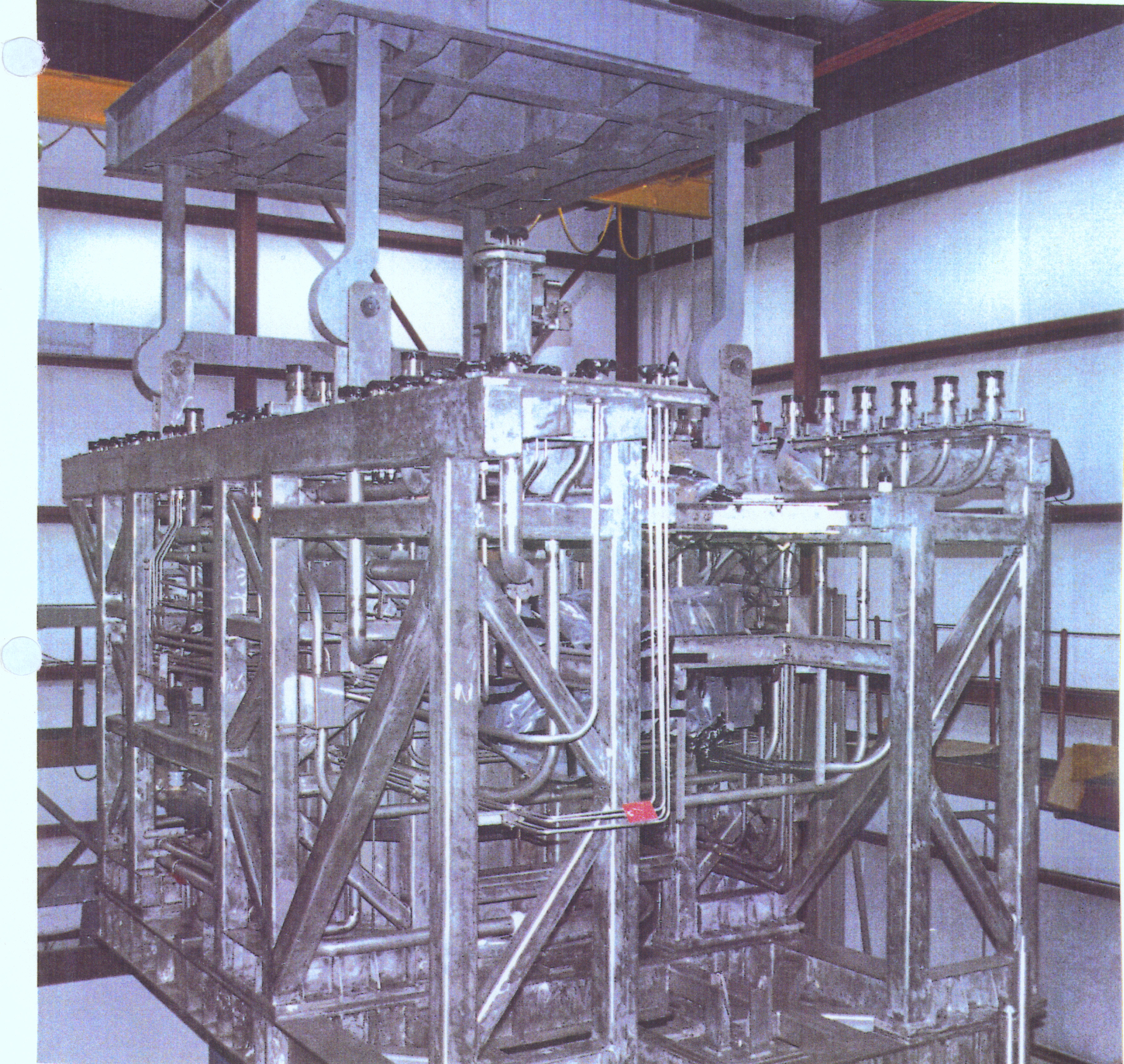
Figure 4.2 - DWPF Melter Assembly
The DWPF Melter is composed of various components that are quite bulky and heavy. Table 4.1 summarizes the weights of the major components3. Table 4.2 gives the densities of the various refractories in the DWPF Melter. These refractory blocks are heavy. For example, a typical block of K-3 weighs close to 700 pounds.
Table 4.1 – Weights of DWPF Melter Components
|
Component |
Weight (pounds) |
|
Vessel |
38,800 |
|
Frame |
28,400 |
|
Refractory |
55,600 |
|
Components |
21,600 |
|
Piping |
2,700 |
|
Nozzle Material |
2,000 |
|
TOTAL |
149,100 |
Table 4.2 – DWPF Melter Refractory Densities
|
Refractory Material |
Density (lbs/ft3) |
|
Monofrax K-3 |
240 |
|
Zirmul |
190 |
|
Korundal XD |
181 |
Not only is the DWPF Melter large and heavy, it was not designed to be remotely disassembled. For example, the melter lid is attached to the rest of the melter with 56 bolts that are tightened and then tack welded in place. This lack of design for remote disassembly is also seen in that most of the major melter parts (like the lid) do not have large eye bolts, etc. that can be used to remotely remove them. Figure 4.3 shows the melter lid being installed. The remote removal of the lid and other components will be a challenge.
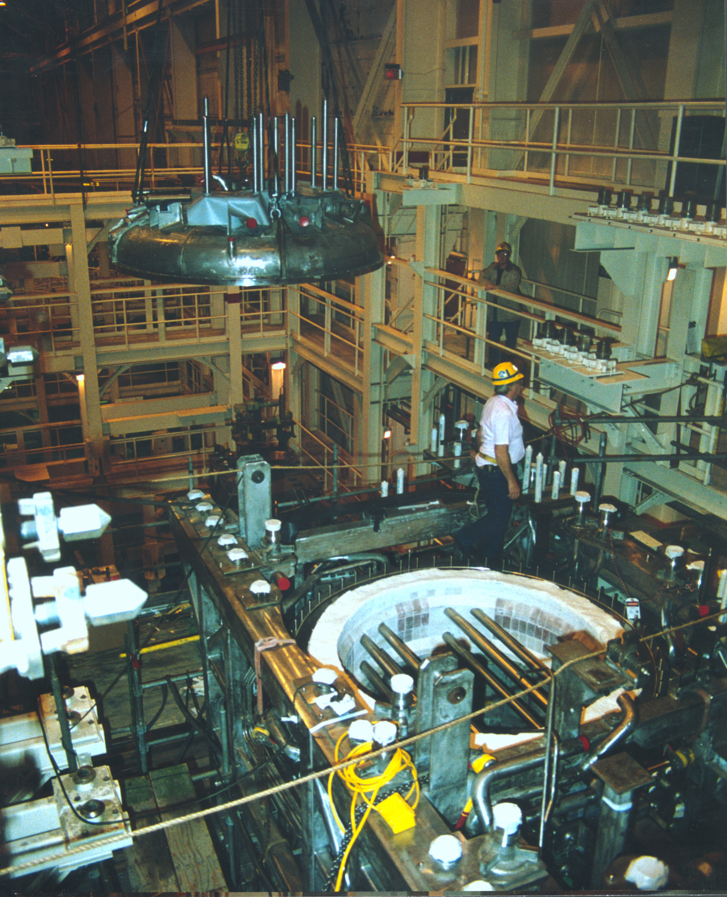
Figure 4.3 – DWPF Melter during Installation of Melter Lid
5.0 Previous Melter Dismantlement Experience
There has been limited remote experience with the disassembly of HLW melters. There have been several pilot-scale or full scale melters that have either been inspected or disassembled after being used in non-radioactive testing. This section discusses these activities.
5.1 Integrated DWPF Melter System (IDMS)
The IDMS was a one-ninth scale, non-radioactive (based on a glass production rate of 25 pounds per hour) DWPF pilot system located at the SRS. It was comprised of feed preparation, melter (two foot inner diameter), and off-gas systems. It was the first and only DWPF pilot-scale melter system that was capable of processing mercury and flowsheet levels of halides and noble metals. The IDMS Melter was shutdown on June 30, 1995 in preparation for inspection. The melter had been operating continuously since October 1988. A total of 15 melter runs, mostly with flowsheet levels of noble metals, were conducted with the IDMS. The melter was still operational at the time of the shutdown although deposits of noble metals on the melter floor were requiring higher current from the lower electrodes to keep the lower melt pool in the acceptable operational temperature range.
Findings pertinent to melter manual disassembly work are as follows4:
5.2 Scale Glass Melter (SGM) Inspection
The Scale Glass Melter was a two-thirds scale (four foot inside diameter) non-radioactive pilot melter of the DWPF Melter. This melter was operated at the SRS between 1985 and 1988. Before the melter was shut down a sequence of "high-risk" tests were conducted. The SGM was first shutdown when it was full of glass. It was then restarted and subsequently drained. The melter was then restarted again by the DWPF startup sequence after being filled with DWPF startup frit. All of these tests thermally cycled a melter that was over two years old. After these tests additional feed tests were run before the SGM was drained and shut down again. After this work the melter lid was manually removed and the refractories were visually inspected. Additional inspections and documentation of this work were not performed due to a cut in funding for this task.
The main finding of the visual inspection of the SGM after all of this thermal cycling was that the K-3 was basically intact with some minimal wear at the melt line. Therefore there is a good chance that the K-3 in a DWPF Melter will be intact even if it drained or shutdown and restarted full of glass. On additional observation was that the lid heaters had not sagged even though they were operated at 1000° C during the melter restart.
5.3 West Valley FACTS Melter Disassembly
At the West Valley Demonstration Project (WVDP), non-radioactive vitrification processing operations were conducted from 1984 to 1989. These operations were called Functional and Checkout Testing of Systems (FACTS) and used a slurry-fed ceramic melter (see Figure 5.1) similar to the one now in radioactive operation at the WVDP. After the FACTS were completed, the melter was removed and manually disassembled. The melter was then inspected to determine the impact on the melter internals due to five years of glass processing. The following gives the sequence of steps used to disassemble the melter5:
An additional comment given was that remote disassembly on the actual radioactive WVDP melter will require methods to break through a rigid crust and thick layers of glass (up to six to eight inches on the bottom) to get to the refractory. Various remotely operated jackhammers, scissor jacks, hydraulic spreaders, etc. will be required. If jackhammers are used, the refractories will be in multiple broken pieces of various sizes.
Figure 5.1 – West Valley Melter
5.4 Pamela Vitrification Plant Radioactive Melter
The Pamela plant in Dessel, Belgium was designed to vitrify high-level liquid reprocessing waste. The plant used a ceramic-lined melter as shown in Figure 5.2.
The plant is somewhat unique in that is was designed to handle the remote dismantling of large HLW equipment such as the melter. Vitrification operations were started in 1985. After the initial vitrification program was completed in 1991, two melters and other large scale equipment had to be dismantled so that the plant could be reused for a second vitrification program that was planned to be started in 1999. From October 1991 till March 1994 one melter and three other large pieces of equipment were dismantled and dismantling waste was conditioned. In total 187 drums (200 liters each) containing cemented medium-level waste were transferred to the appropriate on site facilities. Some five tons of low-level dismantling waste was transferred as well. An excellent summary of the dismantlement work can be found elsewhere and can be viewed at the website address http://208.200.37.252/archiveL.html under the author name Luycx.6 Both melters are 2 x 2 x 2 meter cubic shapes that weigh about 18 tons. Table 5.1 summarizes the basic melter parameters.
Figure 5.2 – Cross-Section of the Pamela Melter
Table 5.1 – Pamela Melter Parameters
|
Melter Parameter |
Dimensions, Value, or Quantity |
|
External dimensions |
2.0 x 2.0 x 2.0 meters |
|
Overflow unit dimensions |
0.7 x 0.9 x 0.8 meters |
|
Refractory material (weight and volume) |
5.2 metric tons – 1.4m3 |
|
Insulation material (weight and volume) |
7.3 metric tons – 5.4m3 |
|
Built-in metallic components (weight) |
2.0 metric tons |
|
Stainless steel containment (weight) |
3.5 metric tons |
|
Glass (weight and displacement) |
0.8 metric tons – 0.3m3 |
|
Total weight |
18.8 metric tons |
Although the plant had a dismantling cell, it was decided to perform the dismantling operations in the melter cell. Both the melter cell and the dismantling cells are equipped with a heavy-duty manipulator. The melter cell also has a 2-ton overhead crane while the dismantling cell has a 20-ton overhead crane. The melter cell has three lead glass windows (1.0 x 0.8 m) at ground level with master-slave manipulator pairs at each window. Three more windows are located on the second level (4 meters higher). Two of these higher windows have master slave manipulators as well.
The design of the melter cell and the dismantling cell took into account the ability to dismantle the melter and process the dismantling waste. This design included having these two cells close to each other and having an adjacent intervention cell that allowed for the maintenance of the cell cranes and heavy-duty manipulators.
The dismantling was done by using existing manipulation systems and by adapting traditional tools like grinding discs, impact wrenches, vacuum cleaners, hydraulic jacks, hammer drills and grab tools for remote work. The dismantling cell was used for the conditioning of the waste into cement.
Because cell ventilation air passes through HEPA filters, no plasma torches could be used for cutting up large components in the cells. Therefore diamond-encrusted blades with a diameter of 230 mm were first used. This produced a cutting rate of about 7 to 11 mm per minute for stainless steel plates that were 3 to 8 mm thick. These low cutting rates lead to the use of grinding discs that obtained the cutting rates shown on Table 5.1.
Table 5.2 – Pamela Melter Cutting Rates for Stainless Steel
|
Tool |
Thickness (mm) |
Cutting Rate (mm/min) |
|
Diamond blade |
3 – 8 |
7 – 11 |
|
Grinding disc |
3 |
700 – 850 |
|
Grinding disc |
5 |
350 – 450 |
|
Grinding disc |
10 |
180 – 230 |
The melter glass containment refractory was ER 2161 RT. The initial plans were to use a diamond-encrusted blade saw to cut this refractory. The installation and use of this saw were deemed to be fairly difficult. Therefore a hydraulic jack with a 31-ton capacity and a stroke of 155 mm was successfully used. This technique was proven to be cheaper and faster. These bricks resist to a pressure of 3,500 kg/cm2 at room temperature. For reference, the compressive strength of the K-3 refractory bricks used in the DWPF Melter is 1406 kg/cm2 per vendor literature.7
The following gives the Pamela Melter dismantling sequence used.
The work was completed within 2.5 years (from 1992 through 1994) with about 25,000 man-hours. Total cost was about 3.5 million dollars. Several lessons were learned from this task and are summarized below.
5.5 Relevant DOE D&D Activities
There have been several DOE funded D&D activities that are relevant to the dismantling of large radioactive equipment. A TFA report entitled "Melter Glass Removal and Dismantlement" from ORNL8 summarizes these various activities. These activities include the D&D Chicago-Pile No. 5 (CP-5) research reactor, the size reduction of the Tokamak Fusion Test Reactor (TFTR) Vacuum Vessel, and D&D work at the INEEL South Tank Farm in January 2000. Technologies used included the Dual Arm Work Platform (DAWP) at CP-5 (DAWP developed by ORNL), diamond wire cutting by Bluegrass Concrete Cutting, Inc. at the TFTR, and the Modified Brokk Demolition Machine (at the STF). Other work sponsored by the D&D Focus Area include supporting demonstration of the oxy-gasoline torch, a self-contained pipe cutting shear, and a size-reduction machine. Additional details of these activities and other commercial capabilities can be found in the above-cited report (can be found at website address http://www.ornl.gov/~webworks/tlp/tlp_web.htm ).
A jointly written report from SRS and ORNL gives an outline for large-scale system operations and D&D work. 9
Finally, an SRS report describing the conversion of a section of one of the separations buildings at SRS from a remote-crane-operated facility into a master-slave-manipulator-operated facility will give some insight into what it might take to convert an existing radioactive facility into a remote dismantlement facility.10
This work included equipment removal and building decontamination. It also included the installation of new service and support equipment, the analytical support equipment support equipment provided within the facility, the process equipment originally installed for separating and purifying Cf252, and the computer-based monitoring system for on-line control of the ion exchange process.
6.0 Current DWPF Melter Storage/Disposal Plan
During the design of the DWPF, special cells and equipment was considered for the dismantlement of failed DWPF Melters but was deemed too expensive to be included in the project. Therefore the current long-term storage/disposal plan for failed DWPF Melters is as follows.
There are now two existing FESV’s at DWPF. Each FESV is a reinforced concrete structure designed as a Category 1 facility. The FESV provides facilities for removing, transporting, and replacing failed or unusable equipment. Two melter assemblies can be stored in each vault. Permanent storage of these melters in the FESV’s is probably not a viable option as this would amount to using the Savannah River Site as a HLW repository. Therefore, it is assumed that at the end of the life of the DWPF that the failed melters will have to be size reduced and then the parts segregated based on waste classification. This may not have to be done if their radioactive content is low enough to meet incidental waste rules.
This may be accomplished by moving the melter assemblies (one at a time) back into the DWPF Canyon to be D&D’d. There is no formal plan at this time as to how to do this D&D work. The DWPF, however, may not be used to D&D the DWPF Melter. Another existing facility or a new facility designed solely for the D&D of large HLW equipment may be used. Finally, there is the option of shipping these failed melters to the HLW repository. The size and weight of the melter assembly along with the potential amount of HLW glass in the melter will probably make this transportation option impossible. Also, the federal HLW repository design has no provision for accepting and storing a package of this size and weight.
7.0 DWPF Melter Dismantlement
This section describes the basic tasks that will be required to dismantle the DWPF Melter. The exact details cannot be addressed because the location of the dismantlement has not been determined (DWPF, new facility, or modified existing facility). In addition, the details of how the melter assembly is disconnected and moved are not discussed here as these are already covered in existing DWPF procedures or they would be developed by DWPF in the future.
There are basically three different approaches to DWPF Melter dismantlement. The first approach would be to remotely remove enough glass from the melter so that the melter would be considered non-HLW. The second approach would be to dismantle the melter from the outside in. The last approach would be the dismantlement of the melter from the inside out. Each of these options is discussed below. Many of the steps are similar for the various approaches and therefore the tooling required for the tasks are discussed in a later section.
7.1 Glass Removal Approach
The chances of removing enough glass from an intact melter to have the melter disposed of as non-HLW are fairly low. This is because the glass would have to be mined out remotely through the various 4-inch diameter top head nozzles. The glass cannot be accessed via the two 8-inch diameter off-gas nozzles because the dome heaters are directly below these ports. It may, however, be conceivable to take off the melter lid and then remove enough of the glass to store the melter as non-HLW. With regards to the maximum radiation levels for the melter to be disposed of as non-HLW, these numbers and rules change with time. Therefore, the specifics are not discussed here as dismantlement work will not occur for probably another 20 years. This timing could of course be accelerated if multiple melter failures occur due to problems such as the settling of noble metals. The basic steps to perform this dismantlement are as follows.
The main advantage of this approach is that is the simplest and least expensive of the three alternatives. Minimal amounts of size reduction of melter materials would be required. The effort to remove the glass from the melter would be about the same as the other two approaches. The main disadvantage is the uncertainty as to whether or not the removal of the glass would then allow for the disposal of the melter as non-HLW. Also, the details of how to reinstall the melter lid back on the melter (although not required) are uncertain at this time. If repository and waste regulations allow for this approach at the time of disposal, then it is recommended that it be used for the DWPF Melters.
7.2 Inside-Out Melter Dismantlement Approach
This approach is the same type of method cited in the West Valley dismantlement report (described by West Valley as the basic approach).5 The steps are about the same but some steps are added due to the differences in the two melters. The basic steps to do this dismantlement are as follows.
This approach allows the melter shell to provide containment for the refractory pieces, therefore helping to minimize the amount of contamination in the dismantling facility. It also allows for the movement of the melter by the use of the lifting yoke as shown on Figure 4.2 until the melter shell is cut. This approach is similar to the one that was successfully used on the Pamela Melter that was cited earlier6 in section 5.4 of this report.
7.3 Outside-In Melter Dismantlement Approach
In this approach, the melter shell is removed before the removal of the refractory. This approach is similar to the second disassembly alternative cited in the West Valley melter dismantlement report.5 The less contaminated refractory (located at the higher melter elevations) is taken first and then the glass-contaminated refractory is removed. This allows for the bulk of the frame and shell to be disposed of as small pieces of LLW. The basic steps to accomplish this dismantlement are as follows.
The easier to reach/less contaminated refractories are removed first. Unfortunately, there is a greater chance of spreading contamination in the dismantling facility because there is no containment provided by the melter shell. In addition, the glass contact refractories will not be supported when being broken apart. This approach would possibly make the handling of the refractories easier.
8.0 Candidate Dismantling Tools
In considering tools for the disassembly of a melter or other large HLW equipment there are several characteristics of the tools that must be considered. Obviously the tool must be able to perform the task required. Because they will be used in a remote radioactive environment, other criteria should be considered as well. One of these is reliability. If the tool requires constant replacement or repair, then the actual cost of the dismantlement work will greatly increase. The speed at which the tool accomplishes the work along with the ease that is can be done must also be factored. The ease of repair or change out of the tooling is still another factor. Tooling should also be chosen based on whether or not it can be used with the existing manipulators, etc. that are in the dismantlement facility. A final consideration is the amount and type of secondary waste that will be generated by the various tools being considered. Finally, the use of proven technology is a prudent approach when choosing tools for this type of work. The West Valley and Oak Ridge reports have excellent summaries of tooling that could be used and should be reviewed when choosing the final tooling for this task.5,8 The various steps for dismantlement for the DWPF Melter as previously discussed are given in the following sections with tooling that should be considered for each step. Descriptions of some of these tools are given later in this report.
8.1 Removal of Melter Lid
Before the melter lid can be removed, the 56 top head bolts that hold the lid to the melter vessel must be cut. This includes the tack welds from the nuts to the bolts and the nuts to the flange. The best choice for this would be a grinder tool with grinder discs. Grinding discs were successfully used during the Pamela Melter dismantlement.6 These could grind the welds and also the nuts/bolts. Lifting the melter lid remotely was not considered in the design of the melter. There are four lifting holes located on the top of the melter lid that were used to lift the lid during installation (see Figure 4.3). By using manipulators, chains may be able to be reinstalled at these four points to remove the lid. If not, the lid could be raised by accessing the various nozzles. This technique, however, could cause problems by breaking up the melter lid refractories during movement. A lid lifting jig or fixture could also be fabricated. This suggests that a welder to install lifting and handling tabs may be required.
8.2 Breakup/Removal of Refractories
The breakup of the various melter refractories could be accomplished by the use of various tools. These include the following.
The most likely scenario would be to grind or cut the face of the refractories to remove as much contamination as possible. A vacuum system could be used to collect the waste dusting from the grinding process. The use of a jackhammer with the proper force and stroke would then be used to break up the refractory. This was the tool of choice for the Pamela Melter work.6 A heavy-use remote arm with "grabbing fingers" and possibly a modified grapple device (attached to an overhead crane) currently used at West Valley would be used to grab and move the broken up refractory pieces.
8.3 Cutting of Dome Heaters and Top Head Components
The cutting of the Inconel 690 dome heaters (3.25 inch outer diameter/1.25 inch inner diameter) will have to be done with the heaters in place. The cutting may be done by one of the following tools.
If grinding discs are used, a vacuum system could be used to collect the waste dusting. The top head components are also made out of Inconel 690 and have a three inch outer diameter. The feed tube does have Hastelloy C276 0.44 inch inner diameter tube in it.
The grinding disk or a needle gun could be used to remove glass from these components. This would be done before the components are size reduced.
8.4 Breakup/Removal of Glass
The effort needed to breakup the glass will depend on the amount of glass left in the melter. Per past experience with the Scale Glass Melter, there should be about one inch of glass in the DWPF Melter (not counting noble metals deposits) if it is drained completely via the drain valve.11 A failed melter that was not drained, however, could have as much as 16,000 pounds of radioactive glass. The following tools could be used to perform this task.
8.5 Cutting of Melter Frame Assembly and Melter Shell
The cutting of these items could use the following tools. Tools that do not produce secondary waste should be used as much as possible.
8.6 Tooling Descriptions
This section gives brief descriptions of various candidate melter disassembly tools listed in the previous sections. Basic tools listed are not discussed here.
Ram (Free-falling Weighted Chisel) – The RAM is a weighted chisel that is supported in a manner to restrict all but vertical motion. The chisel is lifted to a fixed height and then released to split or chip refractory.
Hydraulic or Mechanical Spreader – This tool consists of two wedges located 180 degrees apart and connected through a double acting hydraulic cylinder or lead screw. These wedges can then be used to fracture refractory or glass.
Shears – Shears consist of two parallel jaws made of thick steel plate material. They can cut structural steel, steel plate, rebar, and concrete.
La Bounty Crusher – This is similar to shears. The jaws are specifically designed to crush brittle material such as concrete and ceramics.
Needle Gun – The needle gun uses a set of metallic needles that rapidly reciprocate to clean surfaces or break up material.
Grapple – The grapple is a tool now used at West Valley. It is comprised of two sets of thick metal fingers that pivot on a common pin. The fingers are interlocked when the grapple is closed. It can be used to grab pipes. By modifying the fingers to make it a clam shell, glass and refractory can be picked up. It can be operated via overhead cranes such as the DWPF Melt Cell crane.
Plasma Torch – Plasma (electrically produced) melts/vaporizes and blows away products.
Abrasive Water Jet – High pressure (30,000 psi plus) water is sprayed through a nozzle with abrasive particles to cut materials. This tool is capable of cutting very thick materials such as metals and refractories.
9.0 Summary/Recommendations
The dismantlement of large SRS HLW equipment, including the DWPF Melter, will be a major undertaking. The current plan is to store failed DWPF Melters in Failed Equipment Storage Vaults located at the DWPF. While this storage is acceptable in the short term, technology and a strategy must be developed to properly dispose of this equipment. Because these failed melters vitrified HLW and may hold up to 16,000 pounds of radioactive HLW glass, they will eventually need to be D&D’d. At this time there is no facility at SRS specifically designed for the D&D of large HLW equipment. The DWPF may be used to dismantle the DWPF Melter at the end of the life of the DWPF. However, an existing facility may be modified or a new facility may be built to D&D large HLW equipment.
It may be possible to take the lid off of failed DWPF Melters and remove enough glass to then classify the melters as non-HLW. This would then allow the melters to be disposed of on site without a full scale D&D effort. If for technical or regulatory reasons this is not possible, two disassembly options are given. Recommended tooling for this work is given. Details of the remote equipment (manipulators, etc) to operate the tooling are not provided, as the facility that it will be done in has yet to be been determined.
The following recommendations are given with regards to this DWPF Melter D&D task at the SRS.
10.0 References