WSRC-TR-2001-00193
Radiolytic Bubble Gas Hydrogen Compositions
J. R. Hester
Westinghouse Savannah River Company
Aiken, SC 29808
This report was prepared as an account of work sponsored by an agency of the United States Government. Neither the United States Government nor any agency thereof, nor any of their employees, makes any warranty, express or implied, or assumes any legal liability or responsibility for the accuracy, completeness, or usefulness of any information, apparatus, product or process disclosed, or represents that its use would not infringe privately owned rights. Reference herein to any specific commercial product, process or service by trade name, trademark, manufacturer, or otherwise does not necessarily constitute or imply its endorsement, recommendation, or favoring by the United States Government or any agency thereof. The views and opinions of authors expressed herein do not necessarily state or reflect those of the United States Government or any agency thereof.
This report has been reproduced directly from the best available copy.
Available for sale to the public, in paper, from: U.S. Department of Commerce, National Technical Information Service, 5285 Port Royal Road, Springfield, VA 22161, phone: (800) 553-6847, fax: (703) 605-6900, email: orders@ntis.fedworld.gov online ordering: http://www.ntis.gov/support/ordering.htm
Available electronically at http://www.osti.gov/bridge/
Available for a processing fee to U.S. Department of Energy and its contractors, in paper, from: U.S. Department of Energy, Office of Scientific and Technical Information, P.O. Box 62, Oak Ridge, TN 37831-0062, phone: (865 ) 576-8401, fax: (865) 576-5728, email: reports@adonis.osti.gov
1.0 Introduction
Radioactive waste solids can trap bubbles containing hydrogen that may pose a flammability risk if they are disturbed and hydrogen is released. Whether a release is a problem or not depends, among other things, on the hydrogen composition of the gas. This report develops a method for estimating the hydrogen composition of trapped bubbles based on waste properties.
Keywords: high level waste, flammable gases, gas retention, gas release, flammability controls
2.0 Summary
A method is developed to predict the hydrogen composition of trapped bubbles in SRS waste solids. Radiation of pure water produces hydrogen and oxygen in a ratio of about two moles to one. The hydrogen composition in waste is a complex product of several variables including:
Nitrate and nitrite ions produce the greatest effect on gas yield and composition, and a method is developed to predict the gas composition produced by mixed-nitrate/nitrite solutions exposed to alpha or beta/gamma radiation.
In laboratory tests, sludge solids were found to lower the hydrogen composition of radiolytic gas, and saltcake was found to produce nitrous oxide in addition to or in place of oxygen. Although the method does not directly address the effects of sludge or saltcake it is shown to yield conservative results (high hydrogen estimates) when these materials are present. Because organic materials consume oxygen, the method cannot be applied to situations where organic concentrations exceed one percent.
3.0 Discussion
3.1 Method
Nitrate and nitrite ions highly influence radiolytic gas compositions. Nitrate is especially influential because it scavenges hydrogen and produces radiolytic oxygen, regardless of its concentration. In contrast, nitrite produces oxygen up 0.5M (molar) concentration and scavenges oxygen above that. Nitrite scavenges hydrogen, but more weakly than does nitrate.
Single-salt solutions of nitrate and nitrite and other anions produce gases that range in composition from about 5 to about 95 percent hydrogen, when exposed to gamma radiation. The gas composition depends on the particular ion and its concentration. These solutions also produce oxygen and small quantities of nitrogen oxides.
Equations (1)-(3) below can be used to estimate the hydrogen composition of gas produced by Co-60 radiolysis of either nitrate or nitrite solutions of any concentration. Then, the next step will be to construct a model for mixed nitrate/nitrite solutions.
3.1.1 Nitrate Effect
Figure 1 is a curve fit of hydrogen versus nitrate data obtained from gamma radiolysis of aqueous solutions. This data is taken from SRS studies [1], except the 2M nitrate value, which is taken from the literature [2]. The data fits the equation:
HNO3 = 0.0242[NO3]3 - 0.076[NO3]2 - 0.2101[NO3] + 0.69, for [NO3] > 0M. (1)
Where, HNO3 is the volume (or mole) fraction of hydrogen in the gas (mole H2NO3/mole gasNO3), and [NO3] is the nitrate concentration in moles per liter (M).
3.1.2 Nitrite Effect
Figure 2 shows two curves used to fit hydrogen versus nitrite data obtained from gamma radiolysis of aqueous solutions. Two curves are used to fit this data because the hydrogen-nitrite relation is complex. The equations of these curves are:
HNO2 = 1.0213[NO2]2 - 1.2235[NO2] + 0.9821, for [NO2] < 1M (2)
HNO2 = 0.035[NO2] + 0.74, for [NO2] > 1M. (3)
Where, HNO2 is the hydrogen fraction (mole H2NO2/mole gasNO2), and [NO2] is the nitrite concentration.
3.1.3 Mixed Nitrate and Nitrite Effect
Theoretically, the hydrogen composition of the gas generated by a mixed nitrate/nitrite solution can be computed from an equation of the form:
HMix = HNO3 * WNO3 + HNO2 * WNO2. (4)
Where, HMix is the hydrogen fraction of the gas generated by the mixed solution, WNO3 and WNO2 are nitrate and nitrite weighing factors, respectively, and HNO3 and HNO2 are as above. The ability to compute HMix depends on the weighing factors, WNO3 and WNO2.
Each term in Equation (4) should have the units, mole H2Mix / mole total gas. Where, mole H2Mix represents the moles of hydrogen generated by a given radiation dose to a given volume of mixed solution, and mole total gas represents the moles of all gases generated.
The total moles of gas can be represented by mole gas = mole gasNO3 + mole gasNO2. Where, mole gasNO3 + mole gasNO2 is the sum of the moles attributable to nitrate and nitrite, separately. The units in Equation (4) can be expressed as, mole H2Mix / (mole gasNO3 + mole gasNO2).
Assuming the moles of gas attributable to nitrate and nitrite are proportional to their solution concentrations, correction factors may be written:
FNO3 = moles gasNO3 / (moles gasNO3 + moles gasNO2) (5)
FNO2 = moles gasNO2 / (moles gasNO3 + moles gasNO2). (6)
Where, FNO3 and FNO2 are the mole fractions of nitrate and nitrite, respectively.
Hydrogen generation rates produced by alpha and by beta/gamma radiation are related to nitrate and nitrite concentrations [3] as follows:
Ga = 1.3 – 0.79*[NOeff]1/3 – 0.13*[NOeff]2/3 + 0.11*[NOeff] (7)
Gb/g = 0.466 – 0.51*[NOeff]1/3 + 0.14*[NOeff]1/3 + 0.0055*[NOeff]. (8)
Where, Ga and Gb/g are the hydrogen yield in molecules per 100 electron volts of radiation produced by alpha and by beta/gamma radiation, respectively, and [NOeff] is the effective nitrate concentration given by:
[NOeff] = [NO3] + ½[NO2]. (9)
These expressions can be used to determine correction factors to account for the nitrate/nitrite interaction in mixed solution as follows:
GNO3 = GMix / GNO3 (10)
GNO2 = GMix / GNO2 (11)
Where, GMix, GNO3, and GNO2 are derived from equations (8) and (9) using [NOeff] values for a mixed NO3/NO2 solution under consideration, for NO3 alone, and for NO2 alone. If both alpha radiation and beta/gamma radiation sources are involved, the G values are weighted in proportion to the radiolytic heat rates from each source. GNO3 and GNO2 are the ratios of the calculated mixed hydrogen generation rate to the nitrate and nitrite generation rates, respectively, expressed as moles H2Mix / moles H2NO3 and H2Mix / moles H2NO2.
Equation (4) may be recast by defining WNO3 = FNO3 * GNO3 from Equations (5) and (10) and WNO2 = FNO2 * GNO2 from Equations (6) and (11) so that:
HMix = HNO3 * FNO3 * GNO3 + HNO2 * FNO2 * GNO2. (12)
Equation (12) has the requisite units [mole H2Mix / (mole gasNO3 + mole gasNO2)], and as the following calculations show, the results obtained with this expression compare favorably with experimental results.
3.1.4 Example Calculation
In a gamma radiation experiment, a solution containing 4M NaNO3 and 2M NaNO2 produced radiolytic gas consisting of 18 percent hydrogen, 80 percent oxygen, and 2 percent nitrogen and its oxides [4]. The hydrogen composition for this solution is calculated as follows:
Step 1: Calculate the hydrogen compositions for solutions containing nitrate and nitrite alone.
HNO3 = 0.182 by substituting [NO3] = 4M into Equation (1).
HNO2 = 0.800 by substituting [NO2] = 2M into Equation (3).
Step 2: Calculate the gas generation correction factors nitrate and nitrite.
FNO3 = 0.667 by substituting [NO3] = 4M and [NO2] = 2M into Equation (5).
FNO2 = 0.333 by substituting [NO3] = 4M and [NO2] = 2M into Equation (6).
Step 3: Determine the hydrogen generation correction factors for nitrate and nitrite.
GNO3 = 0.031 by substituting [NOeff] = 4M into Equation (8).
GNO2 = 0.102 by substituting [NOeff] = 1M into Equation (8).
GMix = 0.031 by substituting [NOeff] = 5M into Equation (8).
GNO3 = GMix ¸ GNO3 = 0.031 ¸ 0.031 = 1.0 by substitution into Equation (10).
GNO2 = GMix ¸ GNO2 = 0.031 ¸ 0.102 = 0.3 by substitution into Equation (11).
Step 4: Combine the results from Steps 1 – 3.
HMix = 0.667 * 1.0 * 0.182 + 0.333 * 0.3 * 0.800 = 0.20 (20 percent) from Equation (12).
3.1.5 Comparison of Calculated and Observed Results
Table 1 compares the calculated hydrogen compositions with observed results for a number of synthetic solutions and actual waste tanks. The calculated value of 20 percent hydrogen for the example compares well with the observed value of 18 percent. Similarly, the calculated value of 9 percent hydrogen for a different solution compares well with the observed value of 8 percent [5]. Further, bubbles in Tanks 40H and 8F respectively contained estimated hydrogen concentrations of 27 and 37 percent [6] compared with calculated values of 28 and 36 percent.
3.2 Other Effects
3.2.1 Sludge
Experiments at SRS found that adding ferric hydroxide and manganese dioxide solids to a test solution to simulate sludge reduced the radiolytic hydrogen composition of the gas from 18 percent to 8 percent [7]. This implies that sludge constituents lower the hydrogen composition of bubbles relative to oxygen. The calculated hydrogen composition for this synthetic sludge mixture is 20 percent versus the observed value of 8 percent (Table 1). Therefore, the method should yield conservative results (higher-than-actual hydrogen compositions) when sludge solids are present.
3.2.2 Saltcake
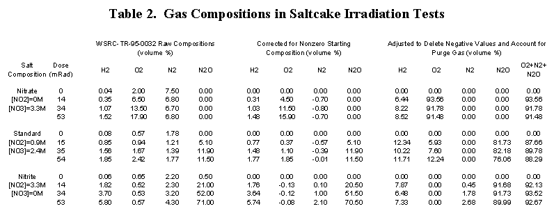
An SRS gamma-irradiation study of three salt formulations, identical except for nitrate/nitrite concentration, found that synthetic saltcake produces nitrous oxide in the presence of nitrite [8].
Table 2 presents the results of these tests. The first set of data columns show that:
The second set of data columns show that nitrate-only and nitrite-only salts produce gas with essentially the same hydrogen composition, except that the diluent is oxygen and nitrous oxide, respectively. Mixed salt produced gas with a slightly higher hydrogen composition in which both oxygen and nitrous oxide were present.
A calculated hydrogen composition cannot be compared with these results because dissolved salt concentrations are not known. However, the results indicate that, although the proportions of oxygen and nitrous oxide change, saltcake produces gases with low hydrogen compositions across the range of nitrate-nitrite concentrations.
3.2.3 Organics
SRS tests show that organic materials in waste consume oxygen at concentrations of one percent and above [9]. Irradiation of a solution containing 0.5 percent tributylphosphate (TBP) and 0.5 percent dodecane produced gas containing 30 percent hydrogen compared with 20 percent without organic additions (Table 1) [10]. If organic materials were present in these concentrations, hydrogen compositions calculated by the method would be non-conservatively low.
Recent analyses found only trace amounts of organic materials in tanks, where they would most likely occur [11]. The organic content of the influents to SRS storage tanks is limited to less than 0.5 volume percent, so the model should be applicable to those tanks [12].
4.0 Conclusions
The method appears to provide accurate estimates of the hydrogen composition of radiolytic gas generated in mixed nitrate/nitrite solutions containing sludge or saltcake. It cannot be applied, however, to tanks containing more than about 1 percent organic constituents. The method appears to be useful, when used within these guidelines, and it should yield conservative estimates of radiolytic hydrogen compositions for use in flammability safety evaluations.
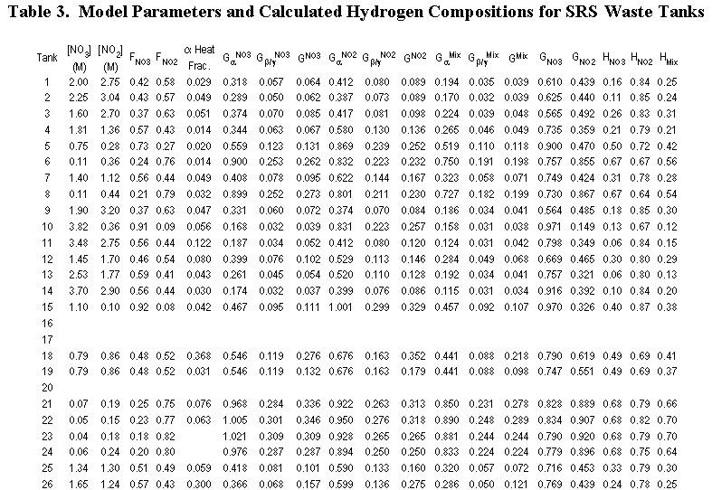
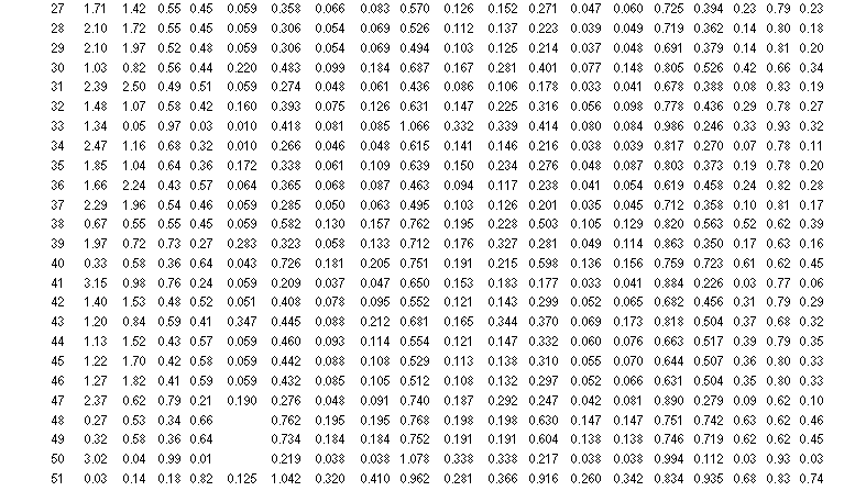
Table 3 lists the calculated hydrogen compositions for each SRS waste tank. Tanks 48H and 49H are included, although the method does not apply to them because they contain benzene. The compositions range from 3 percent for Tank 50H and 6 percent for Tank 41H up to 64 to 70 percent for Tanks 21H–24H and 74 percent hydrogen for Tank 51H. The average composition is 32 percent hydrogen.
These results are generally in line with prior expectations. The hydrogen compositions for Tanks 41H and 50H should be low because they have very high nitrate concentrations, which favor oxygen production. Moreover, the hydrogen composition for Tanks 22H–24H and 51H should be high because they contain very dilute solutions.
5.0 References
6.0 Tables


7.0 Figures

