WSRC-TR-2000-00239, Revision 0
Factors Potentially Influencing the Tackiness of DWPF Streams
David C. Koopman
Westinghouse Savannah River Company
Aiken, SC 29808
This report was prepared as an account of work sponsored by an agency of the United States Government. Neither the United States Government nor any agency thereof, nor any of their employees, makes any warranty, express or implied, or assumes any legal liability or responsibility for the accuracy, completeness, or usefulness of any information, apparatus, product or process disclosed, or represents that its use would not infringe privately owned rights. Reference herein to any specific commercial product, process or service by trade name, trademark, manufacturer, or otherwise does not necessarily constitute or imply its endorsement, recommendation, or favoring by the United States Government or any agency thereof. The views and opinions of authors expressed herein do not necessarily state or reflect those of the United States Government or any agency thereof.
This report has been reproduced directly from the best available copy.
Available for sale to the public, in paper, from: U.S. Department of Commerce, National Technical Information Service, 5285 Port Royal Road, Springfield, VA 22161, phone: (800) 553-6847, fax: (703) 605-6900, email: orders@ntis.fedworld.gov online ordering: http://www.ntis.gov/support/ordering.htm
Available electronically at http://www.osti.gov/bridge/
Available for a processing fee to U.S. Department of Energy and its contractors, in paper, from: U.S. Department of Energy, Office of Scientific and Technical Information, P.O. Box 62, Oak Ridge, TN 37831-0062, phone: (865 ) 576-8401, fax: (865) 576-5728, email: reports@adonis.osti.gov
Executive Summary
An investigation into the potential causes of sludge tackiness in DWPF processing was initiated per HLW/DWPF/TTR-00-0008. The TTR requested in an investigation into possible causal factors for tackiness and suggestions for an experimental program to track/predict tackiness. Increased sludge tackiness is linked to observations at DWPF of increased flush water requirements for process sample loops and lab and process equipment decontamination, as well as shifts in the heat transfer characteristics of the Slurry Mix Evaporator and possible variations in pump and agitator power requirements in the Chemical Processing Cell.
The major conclusions of this report are:
A series of experiments is proposed to quantify tackiness and investigate the effects of various processing conditions on sludge rheology and adhesion. These include, broadly, attempts to define:
Keywords: DWPF, ESP, sludge, rheology, viscosity, colloid, aluminosilicate, adhesion, tacky, surface tension
Introduction
An SRTC investigation into the causes of sludge tackiness in DWPF was initiated per HLW/DWPF/TTR-00-0008. The goal was to research possible causes of such behavior and suggest experiments that could be useful in characterizing tackiness. The current (second) sludge batch, Batch 1B, is more difficult to remove from metal equipment surfaces than the first sludge batch, 1A, requiring additional flush water usage. Other observations include :
These symptoms have been attributed to an increase in the tackiness of the sludge. This report summarizes a preliminary investigation into the sludge characteristics that could potentially influence properties such as rheology, reactivity toward nitric acid, and surface, or interfacial, tension (or energy) as it relates to adhesion to metallic surfaces. Suggested experiments that could help characterize the tackiness of future sludges are suggested.
Background
The Defense Waste Processing Facility, DWPF, has been in the process of vitrifying Batch 1B (also referred to as Macrobatch 2 or Tank 42 sludge) since September 1998. Batch 1A (also referred to as Macrobatch 1 or Tank 51 sludge) processing started in January of 1997 and was completed about September 1998. Preparations are being made for processing the next batch of waste. This will include the contents in Tank 40H, blended with waste from Tank 8F if possible. (Note: H’s and F’s on tank numbers will be dropped after the first usage.) Tank data comes primarily from the Work Group eight (WG08) Excel spreadsheets, such as WCsludge.xls, plus some older SRS hard copy documents grouped together in the References.
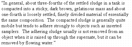
The non-Newtonian nature of Savannah River Site waste sludge was recognized many years ago. An example is the description of waste sludge by M. L. Hyder (DPST-77-415):
Note that the words sticky, gelatinous, and adhere/adhering appear in this brief description. The above comment actually seems to date back to sludge sampling of Tanks 12 and 14 in 1962. Observations of well-mixed dispersions of these sludges showed little appreciable settling over several days.
The following sections are intended to broadly characterize the DWPF sludge processing batch origins based on the original sources of the waste, the waste age, the inter-tank transfer history, the addition of unusual materials, the performance of unusual activities, etc. Waste came from one of two processes, the Purex process of the H Modified (HM) process. Purex waste went to the F-area tank farm. HM waste went to the H-area tank farm. Waste was classified as either high or low heat when leaving the canyons. Mixed heat waste was a blend of high and low heat wastes.
High heat waste was generated on the hot side of the Separations canyons during processing of irradiated targets and fuel. High heat waste initially had to be sent to a cooled tank (not a Type IV). There the high heat waste was held for one or more years before the supernate was decanted to an evaporator feed tank. High heat waste was generated during head-end treatment, first-cycle solvent extraction waste, tank flushes and sump transfers from the hot side of F or H canyon, and aluminum from HM fuel dissolution.
Low heat waste was any waste that was not high heat waste, but was generated directly from reprocessing irradiated fuel. Low heat waste was classified as High-level Radioactive waste per DOE Order 435.1. Low heat waste includes decladding waste (a.k.a. coating waste), second-cycle solvent extraction waste, tank flushes and sump transfers from the warm side of F or H canyon, and B-Line waste. Mixed heat waste was a mixture of high and low heat wastes.
Origin of Batch 1A
Batch 1A consisted of sludge transferred to Tank 51 directly from Tanks 18F, 21H, and 22H and indirectly from Tanks 16H and 17F. An attempt was made to weight the sludge in Batch 1A by tank of origin. Table I gives a breakdown of the sludge solids by tank of origin for two marker species, iron and aluminum
.
Table I. – Contributions to Batch 1A.
|
Origin: |
Iron |
Aluminum |
Waste Type |
|
Tank 16H |
0.01% |
0.13 |
Mixed HM |
|
Tank 17F |
82.14% |
75.81 |
Low heat Purex |
|
Tank 18F |
7.46 |
22.40 |
Low heat Purex |
|
Tank 21H |
1.91 |
0.49 |
Low heat HM |
|
Tank 22H |
8.48 |
1.16 |
Low heat HM |
Tank 18 received low heat Purex waste from August 1959 through March 1961, again from October 1966 through February 1966, once more in June 1971, and again from September 1976 through March 1977. Between December of 1979 and June of 1981 about 99% of the contents of Tank 17F was transferred into Tank 18. Tank 17 was also low heat Purex waste. Between July 1986 and August 1987 the contents of Tank 18, containing the sludge from Tank 17, were transferred into three tanks: Tanks 40, 42, and 51.
Tank 22 received low heat HM waste produced between 1974 and 1980. It also received a small amount of mixed high and low heat HM waste material in November of 1979 from Tank 16. In July 1986 a transfer was made from Tank 22 to Tank 51 of low plus mixed heat HM waste. Tank 22 received low heat HM waste between 1976 and 1981. In November 1979 Tank 21 received the last heal from Tank 16. Following a large transfer from Tank 21 to Tank 42 in 1986, a transfer was made into Tank 21 from Tank 22. Following a second transfer from Tank 21 to Tank 42, the balance of the readily slurried material was transferred to Tank 51. Consequently, Batch 1A was primarily a low heat Purex waste (Tanks 17 and 18) with a small amount of low and mixed heat HM waste (Tanks 16, 21, and 22). The age distribution of the waste was fairly broad.
Origin of Batch 1BBatch 1B consists of residual sludge from Batch 1A plus sludge transferred into Tank 51 from Tank 42. Batch 1B consists of low heat Purex waste and a mixture of HM wastes from six different tanks. Table II attempts to track the origins of Batch 1B in a manner similar to Table I for Batch 1A.
Clearly, Table II illustrates how Batch 1B is a blend of waste blends. It is not clear how WCsludge.xls handled aluminum dissolution. The contribution to the Batch 1B aluminum from Tanks 15 and 16 may be lower than indicated in Table II. The HM waste from Tank 15, plus the Tank 16 material not left over from Batch 1A, were in Tank 42 when the aluminum dissolution demonstration was performed. About 70-75% of the original aluminum went into solution and was decanted away. Tank 15 had also received some Thorex waste prior to being transferred to Tank 42.
Table II. – Contributions to Batch 1B.
|
Origin: |
Iron |
Aluminum |
Waste |
|
Tank 15 (via Tank 42) |
6.65% |
36.06% |
Mostly high heat HM |
|
Tank 16 (via Tank 42; blended into Tank 15) |
3.54 |
17.06 |
Mixed HM |
|
Tank 16 (via Tank 42; blended into Tank 21 prior to adding Tank 22 to Tank 21) |
0.09 |
0.39 |
Mixed HM |
|
Tank 16 (via Tank 42; as a blend with both Tank 21 and Tank 22 in Tank 21) |
0.01 |
0.04 |
Mixed HM |
|
Tank 16 (left over from Batch 1A) |
0.00 |
0.02 |
Mixed HM |
|
Tank 17 (via Tank 42; as a blend with Tank 18 in Tank 18) |
36.98 |
20.56 |
Low heat Purex |
|
Tank 17 (left over from Batch 1A) |
24.64 |
13.69 |
Low heat Purex |
|
Tank 18 (via Tank 42) |
3.36 |
6.07 |
Low heat Purex |
|
Tank 18 (left over from Batch 1A) |
2.24 |
4.05 |
Low heat Purex |
|
Tank 21 (via Tank 42; with only Tank 16 blended into Tank 21 first) |
15.81 |
1.40 |
Low heat HM |
|
Tank 21 (via Tank 42; as a blend with both Tank 16 and Tank 22 in Tank 21) |
0.94 |
0.14 |
Low heat HM |
|
Tank 21 (left over from Batch 1A) |
0.57 |
0.09 |
Low heat HM |
|
Tank 22 (via Tank 42; as a blend with both Tank 16 and Tank 21 in Tank 21) |
2.62 |
0.14 |
Low heat HM |
|
Tank 22 (left over from Batch 1A) |
2.54 |
0.21 |
Low heat HM |
|
Net Tank 15H |
6.65% |
36.06% |
Mostly high heat HM |
|
Net Tank 16H |
3.64 |
17.51 |
Mixed HM |
|
Net Tank 17F |
61.62 |
34.25 |
Low heat Purex |
|
Net Tank 18F |
5.60 |
10.12 |
Low heat Purex |
|
Net Tank 21H |
17.32 |
1.63 |
Low heat HM |
|
Net Tank 22H |
5.17 |
0.43 |
Low heat HM |
There were two transfers to Tank 42 from Tank 21. Both occurred after Tank 21 had been mixed with Tank 16 waste. One transfer occurred before Tank 22 material was added to Tank 21 and the other occurred immediately afterwards. At about the same time, September to November, 1986, Tank 42 received five transfers from Tank 18. The Tank 18 material included Tank 17 material.
There is also a cesium removal column on Tank 42. Zeolite resin is dumped into the tank periodically. Overall, Batch 1B is a blend of different wastes, including aluminum dissolution modified HM, conventional low heat HM, low heat Purex, Thorex, and zeolite wastes. In September and October of 1998, about 86% of the Tank 42 contents was transferred into Tank 51 for the start of Batch 1B processing. Whereas Batch 1A was roughly a 90-97% Purex sludge per Table I, Batch 1B is roughly 44-67% Purex sludge per Table II.
Origin of Batch 2
Batch 2 is forecast to include the contents of Tank 40 and Tank 8. Tank 8 was a dried sludge tank until recently. Tank 8 received Purex low, mixed, and high heat wastes produced from 1956 through 1980. The uranium content is roughly triple that seen in Batches 1A and 1B. No sludge transfers have been recorded for this tank.
Tank 40, like Tanks 42 and 51, is a blend of various F and H storage tank wastes, including Tanks 15H, 16H, 17F, 18F, 21H, and 22H. Table III below attempts to track the origins of the contents of Tank 40 in a similar manner to Tables I and II above.
Table III. – Contributions to Tank 40 for Batch 2.
|
Origin: |
Iron |
Aluminum |
Waste |
|
Tank 15 (from Tank 42) |
0.36% |
3.75% |
Mostly high heat HM |
|
Tank 16 (from Tank 42) |
0.20 |
1.82 |
Mixed HM |
|
Tank 17 (from a blend in Tank 18) |
74.33 |
67.75 |
Low heat Purex |
|
Tank 17 (from Tank 42) |
3.34 |
3.56 |
Low heat Purex |
|
Tank 18 (from a blend in Tank 18) |
6.76 |
20.02 |
Low heat Purex |
|
Tank 18 (from Tank 42) |
0.30 |
1.05 |
Low heat Purex |
|
Tank 21 (from Tank 42) |
0.94 |
0.17 |
Low heat HM |
|
Tank 22 (direct) |
13.49 |
1.82 |
Low heat HM |
|
Tank 22 (from Tank 42) |
0.28 |
0.04 |
Low heat HM |
|
Net Tank 15H |
0.36% |
3.75% |
Mostly high heat HM |
|
Net Tank 16H |
0.20 |
1.82 |
Mixed HM |
|
Net Tank 17F |
77.67 |
71.31 |
Low heat Purex |
|
Net Tank 18F |
7.06 |
21.07 |
Low heat Purex |
|
Net Tank 21H |
0.94 |
0.17 |
Low heat HM |
|
Net Tank 22H |
13.77 |
1.87 |
Low heat HM |
Tank 40 is 85-90% low heat Purex waste from Tanks 17 and 18. Thus, it appears very similar to Batch 1A in its main components. Last year’s transfer of Tank 42 into Tank 40 brought in most of the variety that will be present in Batch 2 (aluminum dissolution waste, zeolite, and Thorex waste at low concentrations).
Factors for Tank Farm Waste Differences
Certain readily identifiable empirical factors may or may not be useful indicators of the processing characteristics of waste once inside DWPF. Many of these factors were discussed in the Batch background discussion above. These factors include:
The above list of factors is long. A shorter, possibly more useful checklist would be:
Waste age was eliminated because it tends to be fairly broad even within a single tank. High, low, and mixed heat waste was eliminated because spreadsheet data only shows the difference as one of dilution of the sludge components, not one of compositional differences. Coal, sand, and Thorex waste were eliminated because their presence is not widespread (though these will probably pose their own unique problems).
An initial screening of the significance of the factors in the short list above could perhaps be accomplished with simulant testing. This would involve preparing some more prototypically produced Purex and HM waste simulants, doing aluminum dissolution tests, drying and re-slurrying tests, washing tests, zeolite tests, etc. Some specific experiments are suggested later in this report.
Relevant Colloidal and Rheological Science
Tackiness
Tackiness is not a technical, or scientific, term. The American Heritage Dictionary defines tacky as "slightly adhesive or gummy to the touch: sticky". Some symptoms of tackiness observed in DWPF processing were given in the Introduction. Adhesion relates to a surface force between two unlike surfaces or particles. (In contrast cohesion relates to a force between like surfaces or particles.) Adsorption, instead of adhesion, is used to describe molecular attractions to surfaces.
Waste sludge is heterogeneous, so it can have internal adhesive (net attractive) forces between its various constituent particles (presumably of different composition), as well as external adhesive forces that act between its various constituent particles and adjacent external surfaces (tank walls, pipe walls, agitator shafts and blades, etc.) These adhesive forces are expected to be functions of the compositions of the materials involved. The picture is complicated by various factors that can alter the magnitude of these forces in colloidal systems, such as the SRS tank farm wastes and DWPF Chemical Process Cell sludge slurries. Sludges which exhibit tackiness can be argued to have relatively high internal and/or external adhesive forces.
The Nature of Colloidal Sols and Gels
The system SRS waste sludge plus supernate is a colloidal solution. The terminology of colloidal science may not be completely familiar. Some terms are not properly standardized in the literature. Therefore a Glossary of common terminology has been included at the end of the report (before Appendix). The classification of sludge as a colloidal solution, or sol, arises principally from the size of particles present (an appreciable fraction in the range of 0.001 to 1 micron in diameter). This includes the fine precipitated particles that almost immediately coagulated into larger flocs of 0.5-5 microns in diameter and resist destruction under shear.
The colloidal particles in a sol can form a loosely linked structure which is easily destroyed by applying shear forces to the solution. The long-term stability of a colloidal sol depends on maintaining stronger electrostatic repulsive forces between individual particles than the corresponding cumulative attractive forces. A stable sol does not readily settle, because there are sufficient repulsive forces present to keep the particles from packing into a smaller volume.
When the reverse situation is true, the colloidal particles coagulate into a denser packed mass, called variously an aggregate or an agglomerate, which can be very difficult to resuspend. Coagulation of particles is itself a complicated process. Particles come together to form aggregates due to the attractive forces between them. The aggregates themselves grow by attracting other particles. The aggregates, however, also attract other aggregates. Two aggregates rarely fit together snugly. The resulting structure of the composite aggregate can range from fairly open and porous to fairly compact and dense. The end result of coagulation depends on whether aggregate growth is primarily via single particle additions (more dense) or via aggregate-aggregate unions (less dense).
Colloidal sols have a ccc or critical coagulation concentration. This refers to the electrolyte concentration of the surrounding solution. When the electrolyte concentration exceeds the ccc, coagulation occurs. For monovalent ions the ccc is typically about 0.15 M. SRS waste streams generally exceed this electrolyte concentration. Colloidal sols having more than one type of particle can have more than one ccc. However, if a complex colloidal system contains different types of particles with opposite surface charge, then spontaneous coagulation of oppositely charged particles is expected. An example would be the mixing of a stable sol of hydrous ferric oxide (presumably with a positive surface charge) with a stable sol of silica (presumably with a negative surface charge).
Particles can coagulate even when in a stable colloidal solution. (In a stable colloidal solution, the repulsive forces between particles are great enough to prevent the formation of a gel or densely packed agglomerate.) Coagulation still occurs, though slowly, when Brownian motion of two particles permits the repulsive barrier to be breached. Consequently, "stable sol" is a misnomer, since the long term fate of the solid particles is coagulation. A similar destabilizing phenomena is observed in flowing systems, and is called shear-induced coagulation. Another method of coagulating solids not commonly discussed is to gradually remove the surrounding solution. This forces the particles into a smaller volume, i.e. makes them closer together on average. Some degree of this phenomena probably occurs when a waste sludge mass is allowed to dry inside a tank.
Figure 1 shows an idealized representation of the attractive and repulsive forces between a pair of two colloidal-sized particles of the same diameter and composition as a function of interparticle distance at various concentrations of electrolyte, C. The far right region (dilute electrolyte) is that of a stable sol. The far left region is that of a coagulated colloid (more concentrated electrolyte). It is noteworthy that the coagulation process is generally, but not necessarily, reversible, i.e. diluting from the far left curve to the far right curve may not lead to a redispersion of the colloidal particles as a stable sol. Tank farm waste is probably more complicated since it contains particles of many sizes, some of which may be tightly-packed/bound while others are weakly bound/unbound.
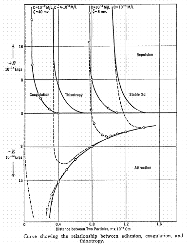
Figure 1. From Inorganic Colloid Chemistry, Vol. III, H. B. Weiser, 1938.
The electrostatic repulsion force which stabilizes a colloidal solution is most effective in a dilute electrolyte solution. The solution should also be maintained at a pH away from that corresponding to the isoelectric point of the solids to maintain the repulsive forces between particles and minimize agglomeration (a fine distinction between isoelectric point and point of zero charge is not considered further here). Isoelectric point is a function of the solid phase composition, as well as the solid surface chemistry and choice of electrolyte. Consequently, isoelectric point data is not a readily tabulated property like melting point.
Table IV presents selected isoelectric point data as ranges for some species of potential interest. The data is from a review by George Parks (1965) supplemented with a few values from Prud’homme and Khan (1996). Precipitates formed using NaOH were favored in selecting the results presented. Synthesized precipitate data, rather than natural mineral data, is given below when both were available. Many of the species below form amorphous colloidal precipitates when synthesized, but are found as crystals in nature. In some instances Parks marked certain data as more reliable, and this is also indicated in the table.
Table IV. – Isoelectric Point Ranges of Oxides and Hydroxides.
|
Material |
Isoelectric Point of the Solid |
|
SiO2 (hydrous) |
1.8 |
|
Albite (NaAlSi3O8) |
2.0 |
|
Montmorillonite |
2.5 |
|
MnO2 |
2.0-4.5 |
|
Ca3(PO4)2 |
~4.6 |
|
Kaolinite (Al4Si4O10(OH)8) |
4.6 |
|
a -Al(OH)3 (Gibbsite) |
3.8-5.2 (choice: 5.0) |
|
TiO2 |
3.5-6.2 (Rutile is ~5.6) |
|
UO2 |
6 ± 0.5 |
|
g -Fe2O3 |
6.1-6.9 (choice: 6.7 ± 0.2) |
|
ZrO2 (hydrous) |
~6.7 |
|
Cr2O3 (hydrous) |
~7.0 |
|
HgO |
7.3 ± 0.3 |
|
a -AlO(OH) (Boehmite) |
6.5-8.8 |
|
g -Al2O3 (similar to Gibbsite) |
7.4-8.6 |
|
Hydrous Fe2O3 and "amorphous hydroxides" |
4.3-8.8 (take: 8.5 for Fe(OH)3 = Fe2O3·3H2O) |
|
PuO2 |
8.6-9.0 |
|
a -Fe2O3 (Synthetic, not natural Hematite) |
8.3-9.1 |
|
Calcite (CaCO3) |
9.5 |
|
ZnO |
9.0-9.7 |
|
CuO, Cu(OH)2 |
9.5 ± 0.5 |
|
Ni(OH)2 |
11.4 ± 0.6 |
|
MgO |
12.4 ± 0.3 |
Figure 2 shows zeta potential vs. pH for boehmite, or AlO(OH), for Hanford waste from Tank 241-SY-102, and for assorted other solids. Zeta potential is the electrostatic charge at a point some distance off the particle surface, i.e. it includes some of the ions attracted to and held by the surface of the particle. The isoelectric point pH occurs at zero zeta potential.
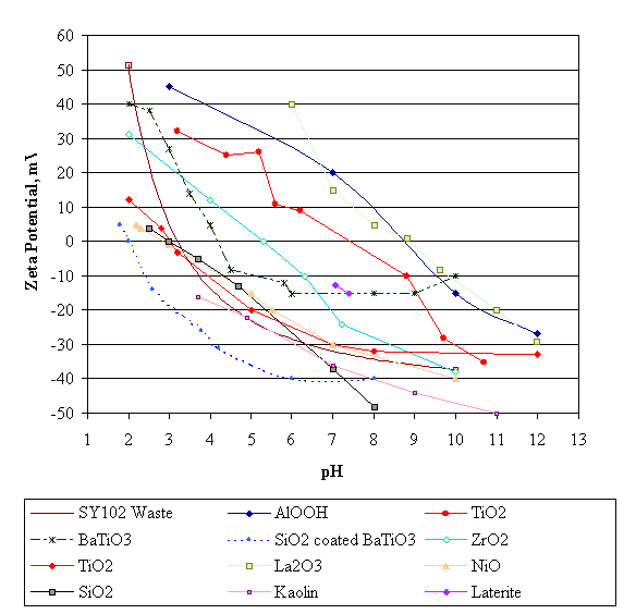
Figure 2. Zeta potential versus pH for selected materials. Slurries exhibit a maximum viscosity
at a zeta potential of essentially zero. WSRC waste contains agglomerates of particles which
would individually have a wide range of surface charge at a given pH.
The species in the figure are primarily insoluble. Enough surplus cation or anion dissolves (over the solubility) from the solid surface at different pH’s to form a net surface charge (negative if more cations dissolve, positive if more anions dissolve). The Figure 2 data for silica and titanium dioxide depend significantly on how the material was prepared, see Table IV above. The isoelectric point for silica has been studied in various systems, and seems to be between about a pH of 1.8-2 (amorphous silica) and three (quartz). (Figure 2 lacks data for hydrous amorphous silica.) Note that the isoelectric point for Boehmite, AlO(OH), of about 8.5 is in the range indicated in Table IV above. The isoelectric point for ZrO2 differs by about a full pH unit between Figure 2 and Table IV. Such variations appear to be the rule rather than the exception, at least with the given technologies being used to make the isoelectric point determinations. Two points for Laterite were included because it is primarily an aged form of Goethite, or FeO(OH). Kaolinite is made of sheets of tetrahedral Si4O10 linked to octahedral Al4O4(OH)8.
The isoelectric point can be found by other experiments than the measurement of zeta potential. One example is electrophoretic mobility. An example of such data is shown in Figure 3. Data is for two sizes of alumina, Al2O3, and for zirconia, ZrO2 (Subbana, 1998). Data was taken in 0.01M NaNO3, with pH adjusted by either NaOH or HNO3. The A16 alumina is roughly a 0.16-micron powder, the zirconia is roughly a 0.3-micron powder, and the SR alumina is roughly a 2.1-micron powder. The isoelectric point of alumina was found to be at a pH of about 7.6-8.1. The isoelectric point of zirconia was found to be at a pH of about 6.0.
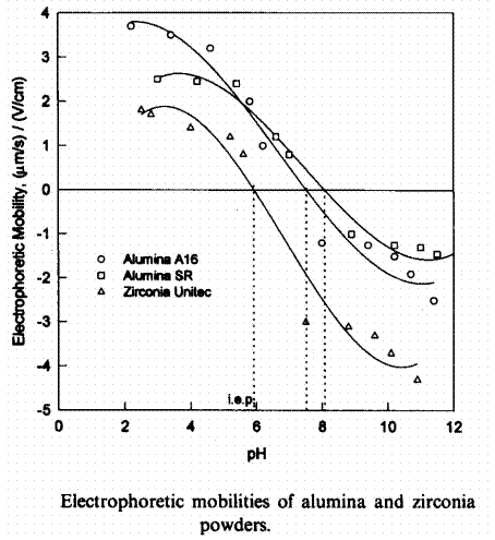
Figure 3. Alternate determination of isoelectric points using electrophoretic mobility, from Subbanna et al., 1998.
Both sizes of alumina have a similar isoelectric point, but it is not clear from Figure 3 whether it is at exactly the same pH or not. Zirconia has an isoelectric point of about 6 here similar to the value in Figure 2.
A falling zeta potential (or electrophoretic mobility) with increasing pH seems to be a universal feature of the data in Figures 2 and 3. When pH is between the isoelectric point of two substances, it is expected that their surface charges will be opposite. Such particle pairs should be strongly attracted to each other. They would be expected to coagulate rapidly, unless one is in great excess, e.g. Fe(OH)3. In that case the particle species in excess might be only partially coagulated by the other species.
The isoelectric point for colloidal sols can also be found from the pH dependence of viscosity. The viscosity of sols generally goes through a maximum at or near the isoelectric point. One interpretation of the viscosity maximum is that work is required to overcome the networking, or bonding, tendency of the particles (strongest at the isoelectric point where repulsion is weakest) and establish the velocity field. Work is input to the fluid through viscous shear. The breakdown of this interparticle bond network is often attributed to an empirical "yield stress" in a plot of shear stress versus shear rate. Yield stress, like apparent viscosity, tends to be maximum at the isoelectric point pH.
Yield stress data from Subbanna for the systems in Figure 3 are shown below in Figure 4. The data are at 25 volume per cent insoluble solids. This gives a fairly high wt. % insoluble solids. Yield stresses increase with decreasing particle size in the alumina data shown. Perhaps most dramatic is the range of the yield stress dependence on pH. The 0.16-m m alumina yield stress varies by over a factor of 50 over a change of 3 pH units. Although yield stresses overall are much smaller for the 2.1-m m alumina, there still appears to be a maximum at about pH 8. This is one paper that actually looked at a slurry with two different solids at the same time. In this case the blend exhibited an intermediate viscosity and isoelectric point from that of the single solid slurries.

Figure 4. The pH dependence of yield stresses for three single component suspensions and a 1:1
zirconia/alumina blend, from Subbanna et al., 1998.
Comparable data for radioactive waste sludges and melter feeds is scarce. Rector and Bunker (1995) studied the Boehmite system in their study on tank waste as described above and shown in Figure 2. They did not fit their data to a Bingham plastic model. Instead they plotted the apparent Newtonian viscosity, i.e. shear stress divided by shear rate, at the (moderately low) shear rate of 11.5/second as a function of pH. They examined two concentrations of NaNO3, see Figures 5 and 6 below. (This apparent viscosity could almost entirely be attributed to yield stress when examining a rheogram, i.e. the Bingham plastic yield stress is not too different from 11.5m /sec and follows the same general trend. For example, if the apparent viscosity, m , at a shear rate of 11.5 seconds is 1000 cP, then 11.5m /sec would be 115 g/cm·sec or 115 dynes/cm2. This gives a poor man’s estimate of yield stress.)
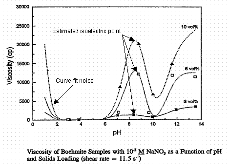
Figure 5. Apparent viscosity of Boehmite slurries as a function of pH in 0.01 M NaNO3. The
isoelectric point is at a pH of about 8.5. From Rector and Bunker, PNL-10761, 1995.
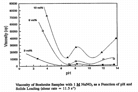
Figure 6. Apparent viscosity of Boehmite slurries as a function of pH in 1 M NaNO3. The
isoelectric point is at a pH of about 8.5. From Rector and Bunker, PNL-10761, 1995.
Warning: do not pay too much attention to the "model" curves in Figures 5 through 9. They sometimes predict large viscosity increases when the solids are all in solution and the solution is a low viscosity Newtonian fluid. Also note that the apparent viscosity scale changes by a factor of three between Figures 5 and 6. The viscosity in Figure 5 for 2.5 < pH < 5 is nearly Newtonian. This might indicate significant dissolution of the Boehmite. The maximum viscosity occurs at a pH of about 8.5 in Figure 5, which corresponds to the isoelectric point of Boehmite, Table IV and Figure 2 given earlier, where the data in Figure 2 for Boehmite are from the same report as Figures 5 and 6 above. The viscosity maxima in Figure 6 near the pH 8.5 isoelectric point are only local maxima. The physical significance of the other maxima at high and low pH in 1M sodium nitrate supernate was not discussed in the PNL report.
The isoelectric point apparent viscosities in Figures 5 and 6 are very similar for the two different sodium nitrate concentrations. Enormous apparent viscosity changes are observed over small changes in pH. Site rheograms of real and simulated sludges and melter feeds all exhibit an empirical yield stress as expected from the above discussion on colloids. No investigation into the proximity of any (real or simulated) SRS waste system rheology measurement to its isoelectric point was located. PNL reports have focused on model systems, or have produced inconclusive data.
J. P. LaFemina et al. (PNL-10763, 1995) give apparent Newtonian viscosity data for hydrous ferric oxide (as Fe(OH)3) as a function of pH at 0.01 M and 1 M NaNO3 and a shear rate of 11.5/sec. These are given below, Figures 7 and 8. Viscosity at a shear rate of 115/sec is also shown on these plots. Somewhere below pH = 3 (depending on the aqueous phase composition) the hydrous ferric hydroxide goes into solution in nitric acid and the fluid is truly Newtonian.
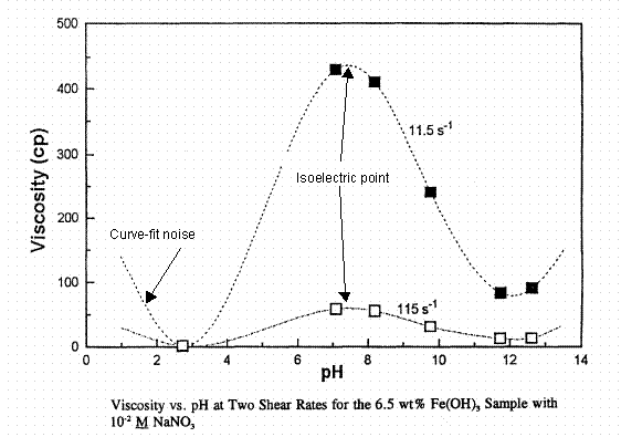
Figure 7. Apparent viscosity of hydrous ferric oxide slurries as a function of pH in 0.01 M NaNO3.
The isoelectric point is at a pH of about 8. From LaFemina et al., PNL-10763, 1995.

Figure 8. Apparent viscosity of hydrous ferric oxide slurries as a function of pH in 1.0 M
NaNO3. The isoelectric point is at a pH of about 8. From LaFemina et al., PNL-10763, 1995.
There is apparently a lowering of the pH at which ferric oxide goes into solution when 1 M NaNO3 solution is present. Solids are probably present at the pH = 2.9 data here unlike Figure 7. The apparent viscosity at the isoelectric point is about 400 cP at both concentrations of NaNO3. Figure 9 below extends the above data to a second solids loading at 0.01 M NaNO3, 13 wt. % as Fe(OH)3 versus 6.5 wt. % in Figures 7 and 8. Note that the viscosity axis covers five times the range of Figures 7 and 8. Both the Boehmite and hydrous ferric oxide systems show increasing apparent viscosity with increasing wt. % solids as expected.
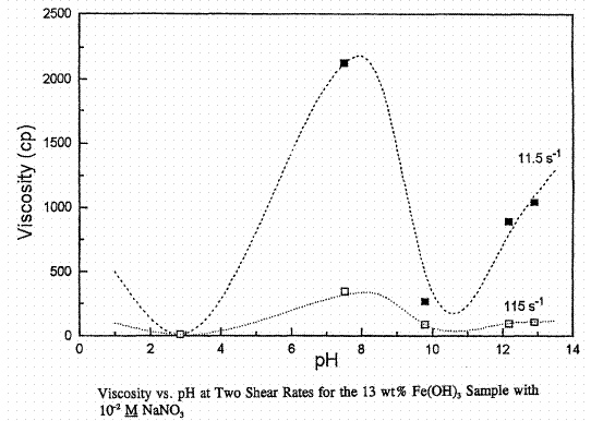
Figure 9. Apparent viscosity of hydrous ferric oxide slurries as a function of pH in 0.01 M NaNO3.
The isoelectric point is at a pH of about 8. From LaFemina et al., PNL-10763, 1995.
The relevance of the proximity of the system pH to the isoelectric point is as follows. The repulsive force between two particles in a sol is transmitted via a cloud of counterions that surround the charged particle surface (counterions are ions of opposite charge to the true charge of the particle surface). At the pH corresponding to the isoelectric point of the solid particles, the net surface charge at the slipping plane (what is believed to be measured by zeta potential, etc.) is neither positive nor negative. In other words a negatively charged particle surface is holding an equivalent number of positive charges (cations) so that the particle appears to be electrostatically neutral from a distance. Particles then have no net repulsive force between them. Most colloidal systems coagulate when they are adjusted toward the isoelectric point. There is a resulting increase in the internal structure between the solid particles as measured by the number of interparticle contacts or bonds per unit volume.
In dilute salt solutions the counterion cloud is diffuse, i.e. not localized close to the particle surface. The repulsive forces (between two counterion clouds of like charge) are then effective at long ranges from the particle center. As salt concentration increases, the counterion cloud is located closer to the particle surface. This contraction reduces the effective range of the repulsive force as the counterions concentrate near the particle surface. Interparticle distances are then more likely to decrease to the point where the attractive forces dominate. When this happens, the colloidal particles generally coagulate into a single larger particle.
One practical example is cited. When SRS canyon waste was first neutralized with NaOH, there was a dramatic change in pH accompanied by precipitation of many small crystals containing the waste cations. Isoelectric point pH’s for various metal oxide and hydroxide species were undoubtedly passed during the pH change. This allowed particles to experience periods of no repulsive force during which they were free to coagulate. Additionally, at some pH values, the potentials of some particle surfaces were positive while other surfaces were negative. These crystalline particles of different composition were even more strongly attracted to each other than crystals of the same composition.
As a consequence, agglomerates containing crystals of various cationic components were formed (such were seen at PNL in their reports discussed elsewhere). As the tank pH continued to increase, some of the agglomerated crystals may have redispersed due to increasing repulsive forces (as counterion clouds reformed between surfaces of like charge). The tank farm pH of about 14 is probably high enough to normally cause a general coagulation of the solids, i.e. the colloidal sol is not stable, it settles/segregates into two phases (liquid and settled solids).
In some cases there is an intermediate state between the stable colloidal sol and a coagulated solid mass. This behavior is also seen on Figure 1 at the intermediate electrolyte concentration region labeled thixotropy. Potentially, there can be a local energy minimum at an interparticle distance greater than that of the coagulated solids. This interparticle separation range is known as the gel state, e.g. gelatin, jellies, etc. Sufficient interparticle structure exists for a gel to show solid-like properties such as elasticity, ability to resist deformation under loads (possibly only small loads), etc. As an example, silica gels can be formed with as little as 1% silica by weight. The remaining 99% (the "fluid" phase) becomes trapped within the network of the gel, i.e. is not free to exhibit fluid-like properties. Some gels can be destroyed by shear forces and become free-flowing colloidal sols again. Generally in that case, however, the gel reforms when the shear force is removed.
A complicating factor in assessing the behavior of SRS waste sludge is the presence of particles of different sizes and types. There would be many curves similar to Figure 1 for each pair of particles. The resulting sludge could conceivably contain both coagulated solid particles (closely packed and bound) and gelled solid particles (loosely packed and more weakly bound, with a trapped aqueous phase). Perhaps a gel phase is responsible for some of the "insoluble" sodium reportedly present in sludge. Variations in interparticle energies could effect the bonding between agglomerates of particles as well as the bonding between individual particles. This fine scale structure is probably not captured by the current procedure for preparing sludge simulant.
The presence of a gel phase in waste sludge could explain a resistance to flushing of lines and surfaces. The fluid portion of the gel is trapped within a network of solids. Flushing may only succeed in moving some of the gel out of the way, i.e. deforming it, so that the flushing fluid can flow past, or drain around, the gelled mass.
One obvious conclusion from the above findings is that site rheological data should only be used at the pH at which it was taken until the significance of pH is better quantified. A second, perhaps less obvious conclusion, is that comparing yield stress and consistency data for two different materials will be open to considerable uncertainty of interpretation. If system A is near its isoelectric point and system B is not, then a higher yield stress for system A should not imply system A is inherently more viscous than system B in a broad sense, only that A is more viscous then B at the pH’s of the two measurements. The isoelectric point yield stress (or apparent viscosity) of B could be greater than the corresponding value for A. That might be the true indication of a more viscous system, and might also correspond to a more tacky system. Conversely, it might by the rheology of the system at its processing pH that relates to observed tackiness.
A third conclusion is that testing over a range of insoluble solids concentration should be performed carefully. The act of concentrating or diluting the system to vary the insoluble solids content has the potential of changing the pH. It is conceivable that the pH change could be as or more significant than the insoluble solids content change. (Fortunately, in the site data discussed below for which pH was reported, pH has changed very little as insoluble solids changed via dilution or concentration.)
Tank Farm Sludge
Wet tank farm sludge is kept near pH fourteen in a fairly concentrated supernate solution. It is almost certainly far from the isoelectric point of the solid particles and above the critical coagulation concentration. Consequently, sludge solids would be expected to have coagulated into a fairly thick mass. A coagulated waste sludge appears to still be less than anywhere from about 15 wt. % insoluble solids for HM waste to over 30 wt. % insoluble solids for Purex waste (based on the rheology work of B. A. Hamm on Tank 8F and 15H unwashed sludge, 1984). This range seems too low. (These waste sludge numbers are in contrast to those for mixtures of granular solids, which typically are 60-95% solids by volume in the literature.) This may be an indirect confirmation of the presence of a gel phase within the agglomerated sludge. The network structure that would be expected to form in the wet settled sludge solids between the larger agglomerates would probably break down under a sufficiently large shear force.
Salt bridges between particles could contribute to the overall sludge structure as salt precipitates from the shrinking supernate volume in drying sludges. Soluble bivalent cations, such as Ca2+ and Mg2+, are particularly effective in bridging the generally electronegative surfaces of two adjacent particles. Such cations generally neutralize only one negative charge on a given surface, leaving the other positive charge available to attract another negatively charged particle.
Other cations can serve as bridging species, including sodium, which is present at a fairly high concentration relative to other cations. Monovalent cations must share their positive charge between two surfaces when acting as a bridging species. Particles can bridge directly if they have patches of non- or poorly-wetted surface. Redissolution of the salt bridges in sludge through dilution will not necessarily destroy direct interparticle adhesive bonds formed between the non- or poorly-wetted surface patches. Practical volumes of redissolution water may not even be capable of dispersing the particles so that the counterion clouds reform.
Conventional levels of shear may be equally ineffective in redispersing the sludge solids. If the solids do eventually become redispersed, the particle size distribution may be found to have been altered toward a larger mean particle size. This implies dispersion was partial, not total. The sludge slurry might then exhibit weaker colloidal characteristics. This could be a potentially positive factor in reducing tackiness, if the tackiness is due to the colloidal character of the sludge slurry. Fewer, relatively weakly attracted large particles would seem to be in the direction of lower tackiness than many, relatively strongly attracted small particles.
Another site example of the action of colloidal phenomena is seen during in-tank washing of sludge. Two competing phenomena are operative. As the concentration of electrolytes in the supernate decreases, the volume of settled solids should increase (because of increasingly effective repulsive forces between the gradually expanding counterion clouds of the particles). The coagulated particles must be able to disperse for this to happen. As washing proceeds, however, the pH falls. This drop is probably in the direction of the mean isoelectric point for waste sludge particles. Repulsive forces decrease as the pH moves toward the isoelectric point.
Which effect is dominant? No site data was found to answer this question, however PNNL has reported increases in settled solid volumes by a factor of from 4-5 during Hanford waste sludge washing (Onishi et al., PNNL-11352, 1996). This suggests that electrolyte dilution, rather than pH, may be more significant in SRS waste processing. A key factor for SRS is that electrolyte concentration usually exceeds 0.15 M. Larger particles would probably redisperse first as the electrolyte concentration falls near the mean critical coagulation concentration. Smaller aggregates should remain intact. Washing probably changes tackiness for a given mass of sludge solids, but the direction of the change is hard to predict.
(Note: poorer packing of particles does not imply a decrease in settling rate. The reverse case actually appears to be more common. Settling rates would probably increase, as the hindering effect is diminished by increased net spacing between particles. Settled volume would probably also increase, as the particles would prefer greater spacing.)
The Problem of Silica
The presence of silica in SRS waste introduces certain problems. A summary of important concepts follows. There is a large volume of literature on silica. Sources were collected together in a group in the reference section at the end.
Silica particles retain their negative surface charge over a fairly wide range of intermediate pH values (due to the low pH value of the isoelectric point of about 1.8). This is in contrast to metal oxides and hydroxides. "Above pH 7, silica forms a supersaturated solution of Si, leading to an oversupply of low molecular weight silica, the excess of which polymerizes to form colloidal particles" (P.A. Smith, PNNL-11040, 1996). The solubility of silica was claimed by Iler (1979) to be between 100 and 150 ppm for 2 < pH < 8. Data in Eitel, 1954, gives solubilities for silica, as SiO2, versus pH ranging from about 50 mg SiO2/liter at pH 3 to about 250 mg/liter at pH 8, i.e. an even larger range than reported above. Eitel’s data may be affected by trace quantities of dissolved metals that can cause increased silica solubility.
The solubility of silica increases when the silica particle surface is convex: the smaller the (positive) radius of curvature, the greater the solubility. At the contact point between two silica particles, the radius of curvature is very small, but negative, and silica solubility is reduced. In this configuration silica tends to dissolve from nearby convex surfaces and deposit around the point of contact, forming a neck between particles.
Silica solubility increases with pH above 8, and at 9 < pH < 10.7, the solubility increase is probably partly due to formation of silicate ion. Above pH 10.7 amorphous silica is completely soluble, i.e. in high pH unwashed sludge silica would have been free to dissolve and reprecipitate as another species. Iler, 1979, reports solubilities at 25° C as 120 ppm SiO2 at pH 6-8, 138 at pH 9, 180 at pH 9.5, 310 at pH 10, and 876 at pH 10.6.
In water the silica sol particles have strongly hydrated surfaces, i.e. º Si-OH surface groups, which can polymerize to Si-O-Si in the course of linking particles together (2 º SiOH = º SiOSiº + H2O). The silica solubility in water increases with increasing temperature. At 25° C, the solubility is about 200 mg SiO2/liter, increasing to about 450 mg/liter at 100° C (Eitel, 1954). The solubility of silica in 3 M NaNO3 solutions at 25° C is about 50% that of silica in water. This again shows the lower solubility in the presence of nitrate ion.
When soluble silicate is mixed with solutions of salts other than those of the alkali metals (Li, Na, K,…), an insoluble amorphous metal silicate is precipitated. The nature of the precipitate can vary widely. The solid phase is amorphous because of colloidal precipitation. Most of the species that are formed this way occur in a crystalline phase when found in nature. When silica comes out of solution, it tends to deposit on surfaces. In sludge processing, any surface, including sludge solid particles, would be susceptible to silica deposition. Furlong (original reference lost, but not Iler’s or Weiser’s books) reported that for oxides, an equilibrium concentration of ~10-5 M (0.6 ppm as SiO2) will ensure that all colloid surfaces will behave as silica surfaces. This work indicates that small concentrations of silica might coat SRS sludge surfaces so that they behave much as silica surfaces would.
Iler (1979) reports that the presence of aluminum in even minute amounts not only reduces the rate of dissolution of silica, but also reduces the equilibrium solubility. In similar experiments it was found that the presence of silica in a suspension of alumina also reduced the solubility of the alumina. Over long periods of time, monomeric silica, as Si(OH)4, reacts with aluminum ion as follows:
2Si(OH)4 + 2Al3+ + H2O = Al2Si2O5(OH)4 + 6H+
The precipitation is most effective at pH 9. Iron has a similar, though weaker, affect at pH 8 (no other pH data found). Polyvalent cations, such as Ca2+, and Mg2+, have been found to decrease solubility or to lead to the formation of insoluble silicates. In the case of calcium the effect occurs above pH 9.5 with the formation of calcium silicate. Zinc also reduces the rate of silica dissolution.
John Fowler (personal communication) mentioned that under the right conditions, colloidal silica acts like a glue that makes clay stick to metal surfaces and inside pipes. Carol Jantzen (personal communication) noted that the high caustic concentration in Tank 42 probably dissolved the zeolite binder, which could have created a sticky sludge. She felt that it wouldn’t be necessary to degrade the zeolite minerals to create the effect. If both phases degraded, then the problem would probably be compounded. (Note that crystalline silicotitanate resin under study for the Salt Alternative problem also has a binder, which might be a source of an entirely new set of problems.)
The solubility of silica is inhibited by the presence of nitric acid, partly because of pH, and partly because of an inherently lower solubility in nitrate solutions versus a nitrate-free aqueous phase. This is discussed further in Eitel, 1954. HCl and H3PO4 are good stabilizers of silica hydrosols, while HNO3 is a good precipitator of silicic acid, H2SiO3. Per Smith or Iler op cit., the silica particles in the presence of salt electrolyte and mildly basic pH would be expected to form a three-dimensional gel network if the particles, e.g. frit, were 20-100 nm in diameter. Since frit is 75-100 m m in diameter, the likelihood of gel formation (due solely to frit) has been questioned for melter feed.
Colloidal silica can be applied to surfaces to either increase or decrease adhesion. When silica particles are anchored to a surface, adhesion of a second material is generally improved. If the silica is loose, adhesion of a second material is usually reduced.
Freshly precipitated silica particles initially aggregate into chains and small three-dimensional networks. These microgels grow at the expense of the sol regions, until the microgels occupy about half of the system volume. At this point, depending on conditions, the aggregation can continue to a gel phase with infinite apparent viscosity. Silica precipitated in the colloidal size range gives solutions that exhibit non-Newtonian fluid dynamics. The degree of non-Newtonian behavior is directly related to the amount of suspended material, and it also depends on the size and shape of the particles.
Coagulation of silica particles is also promoted by the presence of monovalent cations acting as bridging agents. However, above pH 11, the larger potassium, rubidium and cesium ions at high concentration form complete double layers of sufficient thickness to prevent aggregation (only lithium and sodium are effective bridging agents). It is characteristic of divalent cations adsorbed on the surface of amorphous silica that only a single negative charge is neutralized. Coagulation occurs long before the surface of the silica is saturated by cations. The divalent cation acts as a bridge when two silica particles join together. Iron (III) and uranyl ions are adsorbed on silica even at low pH. Mixing colloidal silica and colloidal alumina together leads to coagulation. This coagulate can be destroyed by mixing. It will reform, but more slowly after mixing ends. Repeated cycling (mixing-no mixing) leads to a state where coagulation does not occur when mixing ends.
Silica is an important ingredient in zeolites. Linde IE-95 zeolite is used for cesium recovery in the tank farm. The composition of IE-95 (Jantzen, 1988) is shown in Table V.
Table V. – The composition of Linde IE-95 Resin
|
Oxide Component |
Wt. % |
Mole % |
|
Al2O3 |
13.68 |
6.21 |
|
Na2O |
2.73 |
2.04 |
|
Fe2O3 |
3.29 |
0.95 |
|
SiO2 |
58.30 |
44.93 |
|
CaO |
3.80 |
3.14 |
|
MgO |
1.10 |
1.26 |
|
K2O |
1.19 |
0.58 |
|
H2O |
15.91 |
40.88 |
As seen in Table V, IE-95 resin is nearly three-fifths silica. This silica is free to dissolve and coat the sludge particles of tank sludge waste mixed with resin. Silica coated particles behave differently than the original sludge particles. The alteration of the sludge particle surface material also alters the isoelectric point, and consequently the coagulation and gelling tendencies, etc. Data of this kind was shown above in Figure 2 for BaTiO3 versus silica coated BaTiO3. The isoelectric point fell from about 4.5 for the pure BaTiO3 to about 2 for the silica coated BaTiO3, which is virtually the same as the isoelectric point of hydrous amorphous silica.
The dissolution of silica into an electrolyte solution tends to precipitate other cations as described earlier. Aluminum is a well-studied example. Aluminosilicates are common in nature. Montmorillonite (Al2Si4O10(OH)2·xH2O) is a naturally occurring clay. Its dispersions form a gel (Callaghan, 1974) in sodium solution.
Soluble silica can be precipitated in other forms than those discussed above. Solidification of concentrated radioactive alkaline supernates as either phosphate hydrate or aluminosilicate was an option considered at SRS in the 1970’s (Hale, DPST-73-520). Precipitates included species of the Feldspathoid Group (as opposed to the Silica Group, Zeolite Group, etc., see Berry and Mason, 1959) such as Cancrinite and Sodalite, which both contain a Na8(AlSiO4)62+ group, plus cesium trapped in Pollucite [(Na-Cs)2O·Al2O3·4SiO2·H2O].
Aluminum dissolution of Tank 11 sludge was tested in 1981 (Jones, DPST-81-328). Aluminum dissolution was tested at SRS in the laboratory in the presence of zeolite in 1983 (Motyka, DPST-83-896). Zeolite adversely effected the rate of aluminum dissolution. In 1983 aluminum dissolution was considered for tanks 11, 12, 13, and 15. Tank 15 was transferred to Tank 42 for the full-scale demonstration of aluminum dissolution. As described earlier in this section, silica inhibits the solubility of aluminum in general. This result was seen in lab testing. Here, the aluminum precipitated as an insoluble sodium aluminosilicate, hydroxy sodalite. The inhibition of aluminum dissolution was more pronounced for Boehmite, AlOOH, than for Gibbsite, Al(OH)3.
Zeolite has been found to gradually convert from Chabazite to Natrodavyne and break down from 20-50 mesh particles into finely divided solids (Fowler, DPST-80-488). Degraded zeolite was found to range from ~55 m m in Tank 24 to 1-2 m m in Tank 15.
Sodium aluminosilicates are being found in the tank farm evaporators processing recycle condensate from DWPF as discussed in Wilmarth (WSRC-TR-97-00389). The formation of the species Na8Al6Si6O24(NO3)2·4H2O was studied corresponding to samples from the gravity drain line. This is similar to Sodalite, Na8Al6Si6O24Cl2. The same report claims that frit dissolves rapidly even in unstirred, hot solutions (~95° C, 1 wt. % frit feed).
A report by Beahm et al. (ORNL/TM-13371) on sludge treatment studies gives ternary phase equilibrium diagrams for the system water-Na2O-Al2O3 in their discussion at 30 and 95° C. Sodium aluminates can precipitate under certain conditions even when no silica is present. The paper by Zheng (1997) elaborates on the influence of sodium carbonate on sodium aluminosilicate crystallization in sodium aluminate solutions. The discussion is in the context of the Bayer process for the purification of aluminum from bauxite ore, but there are certain similarities to tank farm chemistry. In the Bayer process, the sodium aluminosilicate forms a scale that interferes with equipment performance. The scale is of the Sodalite/Cancrinite type, i.e. Na8(AlSiO4)6X2·nH2O. X is ½CO32-, ½SO42-, Cl-, or OH-.
Rheology of Colloids
"Tackiness" is expected to manifest in the slurry rheology in some fashion. Therefore this discussion is included as background to indicate some of the generally relevant features of colloid rheology. Hopefully this will also provide a background for questioning the use of the existing sludge rheology data as a tool in estimating relative "tackiness". Yet hopefully it will also show that properly taken data can provide insight into the underlying colloidal nature of waste streams as pertains to tackiness.
Colloidal suspensions can display all known rheological phenomena from shear thinning to shear thickening to time-dependent normal stresses and strong extensional effects. Particle shape, interparticle forces, and the resulting microstructure (sol, gel, or coagulated particles) are responsible for this behavior. The theoretical understanding of the effect of solids on rheology is presently good for dilute suspensions. The fitting parameter of choice tends to be the volume percent of solid present, rather than the insoluble solid weight percent, but in any case does not seem to be the total solids weight percent. Volume percent correlations seem to imply solid particles, rather than porous particles. Theories are emerging for the structure and rheology of colloidally stable, concentrated suspensions.
The state of the art is less satisfactory for flocculated/coagulated systems. Only the qualitative aspects are well understood. Suitable general approaches to manipulate such complex rheological properties as yield stress and thixotropy are essentially lacking. Even the measurement of these properties is not a totally unambiguous process. (Slurry systems free of colloidal size range particles, i.e. having only large particles, generally do not exhibit an appreciable yield stress, and have viscosities fairly close to that of their solid-free solvents.)
The discussion will now elaborate on some of the points above. When a shear field is unable to change the statistical distribution of particles (including any flocculated particles), the viscosity of a colloidal suspension can be nearly Newtonian (R. J. Hunter, 1989). This statement appears to be most nearly true both for very dilute suspensions of colloidal-size particles and for noninteracting coarse (larger than colloidal) particles.
The shear thinning behavior of non-Newtonian fluids, such as colloidal systems modeled with the Bingham plastic equation, has been given a kinetic interpretation. In this interpretation some of the energy input initially goes into structural breakdown of bound colloidal particles, while the remainder goes to overcome viscous drag. When the interparticle structure has essentially been destroyed, the "consistency" becomes nearly constant (at least for spheres). When other shapes than spheres are present, there are hydrodynamically preferred orientations for the particles that can cause curvature in the shear stress-shear rate plot from a rheometer. The number of models proposed to account for these non-Newtonian phenomena is very large. They are primarily empirical.
Some researchers now claim that flow distorts the electrolyte charge cloud around the particles in dilute systems, and thus produces additional stresses. This is called the primary electroviscous effect. In nondilute systems, charged particles can interact. During flow, repulsive forces keep particles farther apart than in comparable neutrally stable systems. As a result, the energy dissipation, i.e. the apparent viscosity becomes greater. This is called the secondary electroviscous effect. Electrostatic forces are not functions of shear rate; therefore their effect is larger at low shear rates than at high rates. This leads to shear thinning and eventually to the appearance of yield stresses (Krieger and Eguluz, 1976).
At very low stress levels, all or most of the colloidal structure persists. The response to shear is either elastic (solid-like) or viscoelastic. The mechanism of flow is more nearly that of creep than flow. A change in structure is generally assumed to be reversible in colloidal systems. Such a change requires time. This can manifest as time-dependent viscosities when taking rheological data. To obtain a reproducible shear stress-shear rate plot, it is important that the relaxation time of the colloidal structure be much less than the incrementing time of the rheometer, or shear ramp rate. Otherwise a gradual erosion of colloidal structure to smaller sizes occurs during measurement at increasing shear rate, followed by reaggregation during the decreasing shear rate portion of the measurement. The relaxation time can be increased by increasing the magnitude of the shear rate applied relative to the mass of sample.
It is also important to understand the limitations of empirical rheological equations of state, e.g. the Bingham plastic and Ostwald-de Waele (or power law) models. These equations are strictly valid for one-dimensional, steady shear flows. They are sometimes used for unsteady-state analyses, but the validity of this approach requires that the time-dependence of the rheological properties under shear be small. They have been found to be broadly inadequate in describing observations for multi-dimensional and/or time-dependent flow problems of non-Newtonian fluids, such as colloidal and polymeric solutions and polymer melts. These fluid flow problems include steady-state tank mixing (multi-dimensional: vortex shape and direction of some secondary flows are incorrect), blending time, pump start-up power, and agitator start-up power (time dependent). Such fluid phenomena, and others, are sometimes collectively referred to as viscoelastic behavior. For example, WSRC waste slurries exhibit viscoelastic behavior.
WSRC has favored the use of the Bingham plastic model to relate shear stress, t , to shear rate, g ,
t = ± t o + h cg ; or t = t o + h cg , when t is positive,
where t o is the yield stress, and h c is the consistency, or plastic viscosity. The shear rate in a one-dimensional, planar flow is given by (-dvx/dy). The plus sign for t o is used when t is positive, and the negative sign when t is negative. (The sign changes occur when using the model in different geometries or with different locations of the origin of the coordinate system.) This model reduces to the Newtonian fluid relation when the yield stress is zero.
The Bingham plastic model has generally fit SRS waste rheometry data better than the Ostwald-de Waele, or power law, model,
t = h p|g |n-1g ; or t = h pg n, if g is positive.
This model reduces to the Newtonian fluid when n equals one, giving h p equivalent to the Newtonian viscosity.
PNNL has used a combination Bingham-power law model (called the generalized Bingham or Herschel-Bulkley model) in some of their reports, where,
t = t o + h cpg n
This model has been the subject of some misinterpretation. For example in WSRC-TR-94-0357, it was implied (Figure 2, page 5 of that report) that the behavior of this model in the limit of zero shear rate, g , gives a curve that is asymptotic to t = t o + h cpg , the Bingham plastic, see Figure 10.
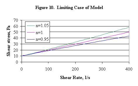
This is not the strictly correct interpretation. When n is near unity, the deviation from asymptotic behavior is not necessarily visible, unless the region of small shear rates is greatly enlarged. The actual behavior is as follows: for n > 1, the slope of the model goes to zero (horizontal) as the shear rate goes to zero, and for n < 1, the slope of the model goes to infinity (vertical) as the shear rate goes to zero. Thus, this model can easily understate the shear stress required to induce motion in a fluid at rest, because it tends to underestimate the effective yield stress when n < 1. An extreme example to illustrate this is shown in Figure 11 below, where no effort was made to find a "best fit" over the shear rate interval 25-225/second.

Here "tau" is t o. "Eta" is either h c for the first curve or h cp for the second and third curves.
Another issue with the Herschel-Bulkley model is the interpretation of the exponent of shear rate, n. When n is less than or equal to one, the fluid is shear-thinning. Shear-thinning is defined to mean that the calculated Newtonian fluid viscosities (ratios of shear stress to shear rate) decrease, or thin, with increasing shear rate. For the Herschel-Bulkley model with non-zero yield stress, fluids with n greater than one are both shear-thinning at low shear rates and shear-thickening at high shear rates. PNNL data that were reviewed during this study generally fit to the case n < 1, i.e. pseudoplastic or shear-thinning. Powers, n, were often quite a bit less than unity. Associated with this were Bingham-power law "yield stresses" that were invariably significantly less what would have been derived from fitting the Bingham plastic model like Figure 11. This resulted in less conservative models for making design calculations, e.g. pump motor startup torque. Conversely, it could be argued that as the power "n" deviates from unity, the non-Newtonian character of the fluid is increasing, and this might be a measurable marker that would relate to sludge tackiness.
There are potential implications within the Bingham plastic model for tackiness as well. Consider a simple momentum transport problem: laminar flow of a liquid film down a vertical planar wall (an approximation to drainage of a wet agitator shaft or tank wall). For film flow down a vertical planar wall, the maximum value of the shear stress is given by r gd (independent of the rheological equation of state), where r is the fluid density, g is the gravitational constant, and d is the film thickness (see Bird, Stewart, and Lightfoot, 1960). For a Bingham plastic fluid, the condition for any flow of the film is r gd > t o, the yield stress. As a liquid film thins due to drainage i.e. is not replenished, this condition of critical film thickness will eventually be met.
The amount of residual material left on the surface, ~t o*(surface area)/r g, is seen to be proportional to the yield stress. To a first approximation, doubling the yield stress, doubles the critical film thickness for flow, and doubles the mass of residual material retained on the wall. This could easily be interpreted as a two-fold increase in tackiness. A film with a ~1 mm thickness is expected for t o = 100 dynes/cm2. It would visually appear that it was harder to get the fluid to drain off the surface. Consider this discussion in the context of the spacing between the SME steam coil tubes, where the force during transfer is less than g. What would it take to bridge the gap between coils? (One analogous result to the falling film solution: a vertical pipe filled with a Bingham plastic fluid will not gravity drain if r gR/2 < t o. R is the pipe radius. This is probably not a DWPF plant-scale problem, since the critical radius for a 200 dynes/cm2 yield stress is only about 0.4 cm.)
While this discussion assumes a Bingham plastic fluid exists, that is not really believed to be the case. Real sludge slurries are only well-modelled by the Bingham plastic equation. Bingham plastic fluids do not flow in the presence of shear stresses less than the yield stress, while actual sludge slurries do flow, though very slowly, in the presence of shear stresses below the modelled yield stress. The physical interpretation is that the colloidal particles retain some degree of structure, or bonding, at all times (the shear rate is too low to keep it disrupted). Motion must occur by the breaking of structure locally (due, e.g. to Brownian motions and collisions of the particles), accompanied by a displacement of some mass (defined to be "flow"), while elsewhere in the fluid structure is being regenerated (i.e. there is a steady-state level of structure among the particles that is transient enough to permit movement). In principle, the structure can become nearly rigid, and all movement, or flow, ceases. The surface of the wall itself can participate in this process, by adsorbing colloidal particles, i.e. adhesion. Colloidal particles forming temporary bonds with adsorbed particles or with other particles that are temporarily bound to wall particles will not appear to move. Nor will the surrounding liquid films of these particles, containing the electrostatically bound counterions, appear to move.
Dispersing Agents
Chemicals that disrupt the aggregation of solids are called dispersing agents, or dispersants or stabilizers. The most historically significant dispersants (Stein, 1996) are the condensed phosphates. These are any dehydrated, condensed orthophosphate for which H2O/P2O5 is less than 3:1. Two examples are tetrasodium pyrophosphate, Na4P2O7, and sodium hexametaphosphate, a.k.a. Calgon, which is approximately NaPO3. John Fowler (personal communication) described using potassium or sodium silicate as a dispersing agent for kaolin clay. Ultimately they found that sodium hexametaphosphate was superior and was stable over a wider pH range, and they stopped using sodium silicate.
Organic polymers can also perform as dispersants. Organic polyelectrolytes are preferred. Some of those being used include polyacrylates, copolymers of acrylic acid with another monomer, organic phosphonates, polysulfonates, sulfonated polycondensates (e.g. naphthalene-formaldehyde sulfonated polycondensates), and naturally occurring polymers such as tannin, lignin, glucosides and gluconates, and alginates. Polyacrylates and organic phosphonates are used in clay processing and as drilling mud thinners, as are some of the natural polymers. These two systems seemed to be the closest analogs to waste sludge/melter feed that were discussed by Stein.
Such materials are generally tested to determine the concentration dependence of the stabilizing action against aggregation. Many dispersants actually aggregate particles in very dilute suspensions via bridging. Flocculation is maximal when about half of the particle surface is covered by dispersant. Stabilization predominates when the whole surface is covered. An effective dispersant can generate a significant reduction in the apparent viscosity of a slurry.
Application to WSRC Waste Sludge Slurries
Colloidal Species in WSRC Waste Processing
The three volume series by H.B. Weiser on Inorganic Colloid Chemistry, I-The Colloidal Elements, II-The Hydrous Oxides and Hydroxides, and III-The Colloidal Salts, formed a starting point for identifying colloidal species in waste sludge. The inescapable conclusion is that WSRC potentially has dozens of different colloidal species that formed during the caustic precipitation of HM and Purex wastes in the Tank Farm. A list of likely candidates, discussed in the series above, is included in the Appendix, Colloidal Species Potentially in Waste Sludge. PNNL has identified numerous multi-cation species in their wastes in addition to the simple species given in the Appendix.
New colloidal species form during processing (ESP, DWPF). Sludge washing probably forms no new colloidal species. However, existing agglomerates of colloidal species may change size as the salt concentration decreases, and as some of the colloidal solids possibly redissolve.
The waste sludge pH is changed from about 12 to 5 by the addition of nitric acid and formic acid in the DWPF Chemical Processing Cell Sludge Receipt and Adjustment Tank, or SRAT. Solubilized aluminum precipitates, probably as a new colloidal species. Mercury oxide reduces to an elemental colloidal liquid phase. Potentially, some of the noble metals (Ag, Pd, Rh, Ru) may reduce as colloidal solids, though this is less certain due to the very low concentrations. Noble metals may instead form small crystallites attached to other sludge particles. This would translate into a trivial increase in the number and weight of colloidal particles in the system.
Rector and Bunker (PNL-10761, 1995) applied electron microscopy to Hanford "NCRW" (neutralized cladding removal waste) sludge particles. Particles of about one micron in diameter were observed to actually be aggregates of hundreds of colloidal size crystals, or crystallites (tiny crystals). Transmission electron microscopy suggested that aluminum was present in three major forms: as extremely fine particles (<10-nm crystallites) of Boehmite, AlO(OH), as 1- to 40-m m particles of gibbsite, Al(OH)3, and as aluminosilicate clay-like minerals that are submicron in size. Iron was present as Fe(OH)3, or Fe2O3·3H2O, which has similar surface charge characteristics to Boehmite (isoelectric points between 8-9 as discussed earlier). Recall, Table I, that Gibbsite has a much lower isoelectric point than boehmite.
The Fe(OH)3 was present in Hanford waste as submicron-sized primary particles like the Boehmite. (Primary particles are the building blocks of the aggregates and exhibit a high degree of crystal structure.) Fe(OH)3 formed ~1.6-m m agglomerates that were almost impossible to disperse regardless of solution conditions, unlike the Boehmite. (Possibly, the electrolyte concentration was always above the critical coagulation concentration of hydrous ferric oxide.) The Fe(OH)3 was also less soluble than the AlOOH at all pH values. The Boehmite crystallites were more plate-like, while the Fe(OH)3 crystallites were more equiaxial (block-shaped). Most of the primary particles in the agglomerates were less than 0.1-m m in diameter.
The Hanford waste agglomerates were open (fractal) structures, i.e. they were considerably larger in volume than would be expected for their mass. Such particles behave very differently from primary particles, e.g. ~solid crystals, of the same diameter, i.e. a 2-m m agglomerate of 10-nm AlO(OH) crystals does not behave the same as a 2-m m crystal of Al(OH). The presence of multi-cation crystallites was also indicated by their data containing the following groupings: (Al, Si), (Fe, Cr), (Al, Zr, U), and (Al, U), plus single cation crystallites containing calcium and zirconium. (Data was from Tank 105-AW.) It may be that the Boehmite particles joined with the hydrous ferric oxide during precipitation because their similar surface charges were too weak to prevent coagulation. The presence of a surrounding ferric hydroxide matrix may have limited the size of the boehmite crystallites relative to the gibbsite crystals.
It is almost certain that the sludge solids pass back through their mean isoelectric point during acid addition in the DWPF SRAT cycle (the first time was during caustic addition to the original waste). This transition should be accompanied by a measurable increase in agitator power draw at constant agitator rpm. Tracking of this data, if available, might be a simple way of monitoring the rheological drift from one SRAT batch to another. It would require adherence to a relatively stable acid addition strategy, a relatively stable delivery of well-mixed sludge from the Tank Farm, etc., since agitator power is also affected by other variables such as wt. % total solids.
The effects of pH on rheology and on interparticle forces have been observed with simulants. In lab and pilot-scale experiments of the SRAT cycle, the visible degree of mixing declines in the middle of acid addition. Formic acid solution actually starts to pool on top of the mixed sludge which is almost a gel. A similar phenomena was observed in the preparation of Tank 40 simulant at the University of South Carolina. Following precipitation of MnO2, ferric nitrate solution was added, followed by a 50 wt. % NaOH solution. The starting pH was quite low (<2). As the pH approached seven, the slurry seemed to gel. Some of the sodium hydroxide solution pooled on top, but eventually mixed in (at a pH of about 7.5). The slurry was quite fluid again by the time pH had been adjusted to 10.2. Unfortunately, the power draw increase could be mitigated by the increased fraction of tank contents that are essentially stagnant when pH is in the vicinity of the isoelectric point.
Shifting redox or wt. % total solids by more than small amounts could further complicate the analysis of DWPF data to the point that little could be learned. Tracking the power draw of the SRAT recirculation pump used for sampling would be less useful, since it is only run at the beginning and end of the cycle.
Adjusted sludge is transferred into the DWPF Slurry Mix Evaporator, or SME. Here it is brought into contact with glass frit. Frit 200 has a volumetric mean diameter of about 160-m m and a number mean diameter of about 70-m m. Thus frit is not considered a colloidal particle, because of its large size. However, frit is known to coagulate to varying degrees in water, which is why it has traditionally been slurried in dilute formic acid. Formic acid appears to act as a dispersing agent by preventing frit from slowly dissolving and reprecipitating as bridges between different particles. The question should at least be asked whether frit does or does not begin to coagulate with itself or with the sludge particles once frit is added to the SME. A follow up question is whether coagulation is sensitive to the pH of the slurry, which is generally nearing five from below during the SME cycle.
Frit is also a source for silica dissolution (leaching). The solubility of silica increases by about 50% with increasing temperature between 25° C and 100° C. Silica solubility in water is 50-150 ppm between pH 2 and pH 8. Several fates for the dissolved silica are possible. Dissolved silica could immediately reprecipitate as sodium aluminosilicates, it could coat sludge particle surfaces making them stickier, and/or it could go into the bridging region of interparticle contacts to create a more rigid joint. Shortening the time that the SME is hot could potentially reduce silica dissolution from the frit. If the SME is cooled, e.g. from 100° C to 50° C, after becoming saturated in silicate ions, then it is likely that silica will reprecipitate onto available solid surfaces (sludge, vessel walls, frit, etc.). It was mentioned earlier that silica-coated particles are often stickier than the original particles, i.e. are better at agglomerating or coagulating as the case may be. The concentration range of interest appears to be 10-300 mg/liter.
There is a common feature to the SRAT and the SME cycles. The products of both cycles have smaller volumes than the cumulative volume of all added streams. Associated with volume reduction is an increase in electrolyte concentration of the supernate. As described under colloidal properties above, concentrating the salt ions shrinks the counterion cloud surrounding the particles, which in turn increases the likelihood of further coagulation, i.e. of particles (or aggregates) sticking to other particles (or aggregates), or to vessel walls, etc. The SRAT feed is about 6000 gallons at roughly 5 volume % insoluble solids (assuming 17% total solids, 3% soluble solids, and a specific gravity of about 3 for the insoluble solids as primary particles). SRAT product transfers are about 6000 gallons, but the soluble solids have been increased by the acid additions. The SME product is also about 6000 gallons at roughly 17 volume percent frit, so a further reduction of the sludge slurry volume, excluding the frit, occurs from about 6000 gallons leaving the SRAT to 5000 gallons at the end of the SME.
In simulant testing, soluble SRAT solids increased from about 3 wt. % to about 9 wt. % during the cycle on a total slurry basis, and remained there at the end of the SME cycle. These numbers convert to about 3.5%, 12% and 17% soluble solids by weight respectively on a supernate basis. Therefore, the soluble solids concentration of supernate increases by about a factor of five across the CPC (this data was at a ~34% waste loading, and even more frit could have been added).
Decreasing, rather than increasing, electrolyte concentration is probably an aggravating factor to "tackiness". If sludge has a tendency to be tacky, decreasing the electrolyte concentration will probably make it tackier. This conclusion follows from the fact that a decreasing salt concentration supports a less dense, more open structure for the coagulated solids. This gives the solids more freedom to reorient or reattach later, e.g. onto other surfaces. DWPF increased acid addition excess from about 125% to 137.5-150% in switching from Batch 1A to 1B. This would probably have shown up as increased electrolyte concentrations in all the CPC sludge streams downstream of the SRAT, if Batch 1B had not been washed more thoroughly than Batch 1A. The guess is that Tank 42 nets out at a lower soluble solids content than Tank 51. Data to confirm this were not found.
There may also have been a slight increase in SME product pH (as measured by DWPF) in spite of increased acid addition. Batch 1A pH seemed to be a little less than 4 between batches 60 and 85. Batch 1B pH seemed to be a little greater than 4 between batches 100-133. After batch 133, SME product pH went up to between 4.1 and 6.8 over batches 134-141. Increasing pH, when below the isoelectric point pH, would be expected to lead to increased attractive forces and higher yield stresses.
Rheology of Waste Slurries
Two types of rheology data will be discussed. The site has obtained some rheological data (concentric cylinder rheometer) for real radioactive waste sludges and for nonradioactive melter feed simulants. Little data (none recent, and not concentric cylinder rheometer based) was located for nonradioactive waste sludge simulant (washed or unwashed) and no data was located for real DWPF melter feed samples. Outside rheology data was examined for PNNL Hanford waste and simulant measurements, university research data on simple systems, etc. The relevance to this study appeared to be limited. SRS waste does not appear to be unusual in the context of general colloidal slurry rheological data.
Figure 12 is a composite of concentric cylinder rheometric yield stress data for real tank wastes at SRS, some washed and some unwashed (the Bingham plastic model is being used). The temperature is approximately 25° C. The pH is probably at least eleven in all cases. The data comes from many sources. These are listed as a group in the references.
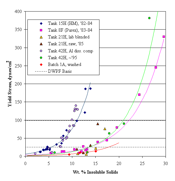
Figure 12. Yield stress of real waste sludges as a function of insoluble solids.
Two features are noteworthy. First, the yield stress data for Tank 51 washed sludge (Batch 1A) was among the lowest reported (red diamonds). Second, the yield stress of Tank 15 HM waste is very similar to that of Tank 42 HM waste following the aluminum dissolution demonstration. This is surprising, since the majority (~77%) of the aluminum had been removed from the HM waste in Tank 42. Both Tank 15 and Tank 42 HM waste appeared much more viscous than either the (primarily) Purex wastes such as Tank 8F, Tank 42 in 1995, washed Batch 1A (Tank 51), or the combined low and mixed heat HM waste data for Tank 21.
The Tank 15 HM waste was mostly high-heat waste, whereas the Tank 21 waste was mostly mixed and low heat HM waste. Possibly this difference somehow accounts for the very different yield stress observations. A significant difference in pH might also explain the difference.
Figure 13 extracts the Tank 42 data from Figure 12. The blending of Purex sludge waste into Tank 42 had a marked effect on the rheology as measured by the yield stress. At a constant yield stress of 100 dynes/cm2, the blended Tank 42 material could hold twice as many solids by weight as the HM material after aluminum dissolution. The yield stress data shown in these two figures seems to indicate that it is not just wt. % insoluble solids that controls the rheology of SRS waste sludge.
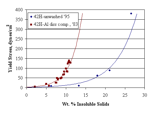
Figure 13. Yield stress data for Tank 42H after aluminum dissolution and after blending
with Purex waste streams, but prior to washing.
Modellers have preferred volume percent insoluble material over wt. % insoluble material for correlating data, but the composition changes of the two Tank 42 sludges in Figure 13 do not admit anything like the factor of two difference in solid crystal density required to bring the curves together. This criticism hinges on the particles being true solid crystals, which the PNNL data suggests is a poor assumption. There could very well be a factor of two difference in the apparent density of the aggregated solids in the two waste blends. Making the measurement on real waste might be difficult.
Figure 14 is a composite plot of consistency data for the same set of wastes just discussed. Data is about at 25° C. The consistency data for the Tank 15H and Tank 42 aluminum dissolution demonstration wastes are concentrated to the left because of their high yield stresses. Much of the scatter in this data may be due to variations in the dilution methods used, the inherent viscosity differences of the respective supernate solutions, the difficulties of obtaining rheological data in the radioactive environment, etc.
Figure 14. Consistency of real waste sludges as a function of insoluble solids.
Figure 15 plots yield stress versus wt. % insoluble solids for various melter feed simulants. Data discovered in the site reports was primarily for Purex based melter feeds from the original coupled process, i.e. contain precipitate hydrolysis aqueous, or PHA, material. Waste loading was presumably standard, although this was not always specified. As was done above, the sources of the data were grouped into their own section in the references.
Figure 15. Composite plot of 25° C melter feed simulant yield stress data.
There is one set of data for Tank 51 (Batch 1A) simulant for the sludge-only process (orange triangles). Most other data lies to the left of the Tank 51 data, i.e. is indicative of higher viscosity. This was also the case for the Tank 51 waste sludge data discussed above. In Figure 15, the yield stress begins to shoot up to values well above the DWPF design basis somewhere between about 37 and 45 wt. % insoluble solids.
The need to run Batch 1B at 1-2% lower wt. % total solids than Batch 1A is hardly surprising given this data. First, the soluble solids content of Batch 1B is lower thanks to greater washing, probably by several per cent in the melter feed tank. Consequently, the insoluble solids could be equivalent to, or even greater than, Batch 1A. Second, given the above data, a shift of several wt. % in melter feed total or insoluble solids should not be unexpected when changing batches.
The effect of pH (see PX4 and Lab-Purex data) is not obvious in this data. Yield stresses of repeated tests showed a lot of scatter. The pH associated with the isoelectric point has not been found in any of these data sets. Without that information, it is not possible to say how far any of the data is from the isoelectric point pH (either above or below).
Hopefully, data presented in the Background section suggested that these melter feeds might be very near their mean isoelectric points at the nearly neutral typical pH values (between five and nine). Since yield stress is maximum at the isoelectric point pH, and falls off to either side, this effect could be completely obscuring the effects of changes in melter feed composition, effects of small changes in wt. % total solids, variations in waste loading, etc. Since determining the isoelectric point rheometrically requires about ten good rheograms at different pH values, it might be better to first adjust all melter feed simulants to three constant pH’s, say 4 ± 0.5, 7 ± 0.5, and 10 ± 0.5 (subject to further study). The goal would be to bound the pH effect on the yield stress.
Figure 16 shows the corresponding plot to Figure 15 for consistency vs. wt. % insoluble solids.
Figure 16. Composite plot of 25° C melter feed simulant consistency data.
The above consistency data is very scattered. Consistency obviously increases faster than linearly with increasing wt. % insoluble solids. Melter feed simulant consistency appears to be lower than that of real sludge in the region of overlap in wt. % insoluble solids. This is likely due to the melter feed frit particles, which are not colloidal and have a lesser effect on viscosity. Consistencies vary by more than a factor of 30. If the soluble solids were all taken as sodium nitrate, then the variation in viscosity of the supernate over the range studied here is less than a factor of two (Anil Kumar, 1993). Kumar gives temperature and pressure dependent parameters, but at low pressure and 25° C, the viscosity of sodium nitrate solutions in water is given by:
m salt/m water = (1 – 0.59xsalt)/(1 – 3.44xsalt)
where xsalt is the mole fraction of sodium nitrate. The viscosity ratio is 1.43 at xsalt = 0.10. The primary factor affecting consistency was therefore concluded to be the presence of the insoluble colloidal solids.
Suggested Experimental Program
A set of experiments varying from simple to complex could be performed to aid in predicting and determining the tackiness of waste sludges and melter feeds. Here are some first pass proposals for experimental programs with their potential relevance to current processing issues. In many cases an integrated approach, where several of the experiments proposed below are done simultaneously, would ultimately be expected to be the most economical. Researchers familiar with the capabilities and limitations of the analytical equipment should be actively involved in better defining the experimental program.
Experiment 1: have real melter feed supernate checked for silica, silicate concentration.
Relevance: saturated silica/silicate ion would imply silica precipitation onto the sludge solid surfaces, with a corresponding increase in stickiness of the coated particles.
Experiment 2: devise a simple test, e.g. dip a 1"x1" square of metal foil into a sample of sludge or melter feed, then weigh sludge-coated foil square after ~60 seconds (duration to be refined). Correlate weight gain of foil to simulant composition, rheology, etc. Test with different foil materials such as glass, steel, etc.
Relevance: need to measure "tackiness" cheaply.
Experiment 3: measure the surface tension of sludges and melter feeds by the Wilhelmy plate or du Nouy ring method.
Relevance: potential correlation of surface tension with adhesion/tackiness. Problem: methods are not geared to slurries. This is a fancier test than just proposed, but the data might be harder to interpret, since there will be certain expectations for realistic ranges of values obtained, etc.
Experiment 4: devise a simple test, using a filter, to measure the filtration time of a sludge sample. Correlate filtration time with tackiness, gel content, rheological properties, etc.
Relevance: need to measure "tackiness" cheaply.
Experiment 5: determine the critical coagulation concentration of sludge or sludge simulant or melter feed simulant. Russ Eibling mentioned that if sludge is washed sufficiently it suddenly expands into a stable sol that doesn’t settle.
Relevance: understand the limits of the materials being processed.
Experiment 6: obtain settling rate data for sludge slurries. Correlate with tackiness, rheological properties, etc.
Relevance: need to measure "tackiness" cheaply.
Experiment 7: test common dispersing agents with simulants to see if an agent might be available that would facilitate decontamination of lab equipment.
Relevance: need already identified in DWPF lab decontamination work.
Experiment 8: check Tank 42 sludge and melter feed for either the soluble or insoluble solids content in addition to total solids. If possible find some Tank 51 sludge and/or melter feed and check it also, otherwise wait for Tank 40 (and 8) processing to start and check it. Sludge and melter feed are more limited rheologically by a maximum insoluble solids content than total solids content.
Relevance: is 50 wt. % total solids harder to hit in Tank 42 melter feed than it was in Tank 51 melter feed because the soluble solids content is lower in Batch 1B?
Experiment 9: it appears that the soluble solids concentration in the tank farm, CPC, etc. are all above the critical coagulation concentration. This may, however, be true only for the original nanometer-sized crystals, not for the larger floc/aggregates. Perform some experiment where sludge solids are slurried in various concentrations of electrolyte bounded by the site waste stream range, subjected to high shear rates, and the resulting particle sizes measured.
Relevance: may affect decisions on the degree of batch washing before feeding to DWPF.
Experiment 10: test aluminum dissolution of a simulated HM waste with complimentary before and after rheology and particle size measurements; repeat test in presence of zeolite; blend products ~50/50 with Purex sludge simulant, wash, and compare rheological properties of washed HM, washed HM after aluminum dissolution (with and without zeolite), washed Purex, and the washed HM-Purex blends. Could potentially continue the tests into a melt rate comparison.
Relevance: the impact of aluminum dissolution on washed sludge properties does not appear to have been studied previously. The interaction of zeolite with aluminum during aluminum dissolution is not clear. This also is an experiment where silica could be tracked.
Experiment 11: do rheology vs. pH and establish the yield stress enhancement at the isoelectric point for both simulated washed sludge, simulated SRAT product, and simulated melter feed. Produce all samples from the same starting material.
Relevance: what does the rheological data we have in hand mean, and what could we do in the future to get data that permits a more ready comparison of different sludges? Should future investigators routinely find the pH of maximum yield stress? If rheology can correlate to tackiness, then must both be measured at the same pH, at the isoelectric point, what? Should a rheology test for comparison purposes always include a shift to pH 3.5-4.5 with concentrated nitric acid to move the sludge away from the vicinity of the suspected isoelectric point maximum in yield stress?
Experiment 12: compare rheology of washed simulated sludges to rheology of radioactive sludges. Support with particle size distribution data. In some cases a custom sludge simulant could be prepared that most closely matches the corresponding waste tank composition.
Relevance: the site has obtained rheograms for a number of real waste streams. How closely do simulants match the real waste rheology?
Experiment 13: compare rheology of real melter feed to that of simulated melter feed. Support with particle size distribution data.
Relevance: all site data for melter feed rheology is derived from simulant testing (primarily at ~26% sludge oxide waste loading). Does this data approximate real waste melter feed rheology?
Experiment 14: compare particle size data of sludge simulants diluted/washed with deionized water and diluted/washed with 1M NaNO3 (adjusted with HNO3 or NaOH to same pH). Will the sludge disperse to smaller sizes in either system?
Relevance: can varying the electrolyte concentration produce a change in particle size that might be associated with altered rheology or adhesive properties?
Experiment 15: attempt to reslurry dried sludge simulant with water, dilute nitric acid, dilute caustic, etc.
Relevance: several waste tanks are dried out and the sludge has been allowed to fully coagulate all its agglomerates into a single mass. What is required to redisperse the sludge sufficiently to wash and process it in DWPF.
Experiment 16: measure rheology of Macrobatch 3 sludge in shielded cells following each wash cycle.
Relevance: this report should prove that the electrolyte concentration affects colloidal structure and that colloidal structure affects colloidal properties such as rheology. The above measurements would help quantify those effects for real sludge waste.
Experiment 17: measure zeta potential of sludges.
Relevance: measuring devices are available, but do not always give good
absolute numbers. Still, it should help define whether sludge behaves more like
silica (iep ~2) or more like hydrous ferric oxide and Boehmite (iep ~8).
Closing Remarks
Sludge tackiness derives from the mixture of colloidal particles that are present in the stream. The tackiness is potentially influenced by many factors. These include the composition of the particles, any modification to the surface properties of the particles that might have occurred during processing, and the electrolyte composition and concentration in the surrounding supernate. Changes in tackiness should manifest as changes in the rheological and adhesive characteristics of the appropriate sludge or melter feed stream.
An overview of colloidal principles provides a necessary background for discussion. A review of site data gives some early insight into the magnitude of possible effects. Batch 1A appears to have been one of the least viscous sludges measured to date. Sludge-only, Batch 1A, simulated melter feed appears to have been one of the least viscous melter feeds measured to date. Although historical rheological data was questioned on the basis of pH relative to isoelectric point, if that ultimately is determined to be either a minor factor, or a non-factor because pH relative to isoelectric point was comparable, then DWPF can expect future processing to resemble Batch 1B more than Batch 1A. That statement is, however, conditional upon some factor such as aluminum dissolution, Thorex waste, higher washing, etc. not having corrupted the properties of Batch 1B.
It is recommended that SRTC take a hard look at the pH dependence of yield stress data of sludge simulants either as part of, or independent of, follow-up work from this report. It may be desirable to attempt to define a standard rheological test for sludges and melter feeds for comparison purposes if a pH region with weak pH effects can be found.
This report has raised many questions concerning the causes of varying tackiness. An involved experimental program has been suggested in this report. However, there are many measurements that would be redundant if several groups of proposed experiments were conducted on the same materials. It is recommended that others more familiar with the capabilities of the shielded cell labs and with the capabilities of various analytical instruments help in defining economical and practical experimental programs.
Glossary
Adhesion – the force binding two surfaces together. It derives from far-reaching attractive forces.
Agglomerate – see aggregate.
Agglomerating Electrolyte –electrolytes, often the ones left over from a precipitation, that promote agglomeration of a colloidal species.
Aggregate – the closely packed particles resulting from flocculation or coagulation. The particle spacing is minimal, and the amount of entrained solution is generally less than in a gel. The refractive index of an aggregate is generally greater than that of the corresponding gel. Particles that are themselves aggregates of finer particles behave very differently in dispersions from comparably sized particles that consist of a single mass, e.g. a single crystal. The difference arises from the fractal (non-integer dimensional) nature of aggregated particles.
Aggregation – a catch all term covering gelling, coagulation and flocculation.
Bingham Plastic – an idealized fluid that exhibits no motion when subjected to shear stresses less than a limiting value.
Coagulant – agents added to water for the purpose of coagulating colloidal material. Successful coagulants generally 1) neutralize the particle charge, 2) give a highly adsorbent hydrous oxide that adsorbs or entangles most of the finely divided material, and 3) promote formation of a gelatinous filtering layer.
Coagulating Electrolyte – an ion (cation or anion) that can effectively offset the strong repulsive forces between the charged surfaces of like particles as its concentration is increased.
Coagulation – the packing together of colloidal particles into an aggregate primarily because of London-van der Waals forces (similar result as flocculation). Particles formed this way often settle.
Colloid – generally a more or less stable liquid solution containing finely-divided solids, typically 0.001-0.10 microns in size. (Larger-sized particles can be present in addition, but the small particles must be present.)
Counterion – ions with the opposite charge relative to that of a nearby surface. They are generally found within or near the "slipping plane".
Critical Coagulation Concentration – the ionic, or electrolyte, concentration above which it is not possible for coagulation of a colloid to occur.
Deflocculation – dispersion of a powder into a liquid.
Dipersing agent – generally added during a dispersion operation, such as shearing or ultrasonics, to inhibit reaggregation of particles.
Dispersion – a suspension of particles in a solution, a sol if colloidal-sized, a suspension if larger-sized particles
Electroviscous Effect – the additional stress required to distort the fluid in the charge cloud surrounding a charged particle.
Floc – aggregates formed from particles
Flocculation – conflicting definitions in the literature. The packing together of colloidal particles into an aggregate due of the action of polymer molecules on the particle surfaces (similar result as coagulation). The packing of particles into a loose open structure like a tuft of wool. Apparently, it is impossible to distinguish between the results of flocculation and coagulation in concentrated mixtures, but there is an observable distinction in dilute sols.
Gel – a colloidal solution exhibiting solid-like properties (gelatinous, jelly); often obtained by concentrating a sol. Silica gel is an example of a hydrogel, a gel formed in water. Gels are generally much more open structures than aggregates, i.e. they can incorporate much larger volumes of solvent within their structures than is typical of an aggregate.
Gelling – linking particles into chains that fill the whole volume of a sol so that there is no increase in concentration (as would occur if the particles settled out).
Hydrosol – a colloidal solution, or sol, in water.
Isoelectric point – condition where the net charge behind the "slipping plane" equals zero. Not the same as the "point of zero charge". The slipping plane region includes ions donated by the solution to form a counterion cloud.
Lyophilic – "solvent-loving", e.g. hydrophilic equals water loving.
Lyophobic – "solvent-hating", e.g. hydrophobic equals water hating.
Peptizing Agent – a species promoting liquification of an agglomerate or gel. Nitrate ion is a peptizing agent for ferric hydroxide, as are chlorides and the H+ ion.
Point of zero charge – a situation where the particle surface charge proper, equals zero, i.e. not counting any adsorbed ions from the solution. Contrast this to the isoelectric point, where the net charge is zero at the "slipping plane".
Protecting Colloid – a colloidal species that forms a, e.g. water soluble, film around a colloidal solid species which would otherwise quickly coagulate.
Relaxation Time – the time required for a system to return to a steady condition, once it has been perturbed in some manner.
Shear Thickening – the apparent increase in the Newtonian viscosity of a (non-Newtonian) fluid as shear stress is increased.
Shear Thinning – the apparent reduction in the Newtonian viscosity of a (non-Newtonian) fluid as shear stress is increased.
Slipping Plane – the location away from the solid particle-liquid interface where the solvent behaves as a real fluid (near the interface the solvent molecules adhere to the surface and are not free to move independently of the solid).
Sol – a colloidal solution, a dispersion of a solid in a liquid, not a suspension.
Surface charge – the net difference between the number of protons and electrons contained in a solid particle; for a given particle, it can be either positive, negative, or zero depending on solvent.
Suspension – a dispersion of coarse (non-colloidal-sized) particles in a liquid.
Thixotropy – a material showing a decrease in apparent viscosity with time at constant shear rate. Generally in dispersions, a certain percentage of particles must be less than one micron in diameter to observe thixotropic behavior. Systems with particles all greater than ten microns in diameter are generally not thixotropic.
Viscoelastic – exhibiting both elastic (solid-like) and viscous (liquid-like) properties.
Wetting – the covering of a solid surface by the surrounding liquid requires a low interfacial energy. If this condition is not met, nonwetted areas of different particles tend to adhere together. These linkages are readily broken by shear.
Yield Stress – the minimum shear stress required to observe fluid motion.
Zeta potential – the effective surface potential. Potentials greater than 20 mV are generally sufficient to stabilize a dispersion.
References
SRS Tank Farm
Davis, T. L., D. W. Tharin, and D. R. Lohr, History of Waste Tank 15, 1959-1974, DPSPU 77-11-26, June 1978.
Davis, T. L., D.W. Tharin, D.W. Jones, and D.R. Lohr, History of Waste Tank 14, 1959-1974, DPSPU 77-11-19, August 1977.
Fowler, J. R., Sludge Composition for Each Tank and DWPF Feed Batches, DPST-84-556, 7/5/84.
Fowler, J. R., compiler, Chemical and Radiochemical Analyses of SRP Liquid Waste, DPST-80-409, May 1981.
Jones, D. W., Tank 11 Sludge Aluminum Dissolving Tests, DPST-81-328, 3/17/81.
McNatt, F. G., History of Waste Tank 22, 1959-1974, DPSPU 79-11-5, April 1979.
McNatt, F. G., History of Waste Tank 23, 1959-1974, DPSPU 79-11-7, April 1979.
McNatt, F. G., History of Waste Tank 21, 1959-1974, DPSPU 78-11-10, October 1978.
General Colloid Information
Bird, R. B., R. C. Armstrong, and O. Hassager, Dynamics of Polymeric Liquids, Vol. 1, Fluid Mechanics, John Wiley & Sons, 1977.
Bird, R. B., W. E. Stewart, and E. N. Lightfoot, Transport Phenomena, John Wiley and Sons, 1960.
Hiemenz, P. C., Principles of Colloid and Surface Chemistry, 2nd Ed., Marcel Dekker, Inc., 1986.
Hudson, E. A. et al., "The Structure of U6+ Sorption Complexes on Vermiculite and Hydrobiotite", Clays & Clay Minerals, 47, 4, 439-457 (1999).
Hunter, Robert J., Foundations of Colloid Science, Volume II, Clarendon, 1989.
Krieger and Eguluz, Trans. Soc. Rheol., 20, 29, (1976).
Oliveira, R., "Understanding Adhesion: A Means for Preventing Fouling", Experimental Thermal and Fluid Science, Elsevier, 14, 316-322 (1997).
Sherwood, J. D., "The Primary Electroviscous Effect in a Suspension of Spheres", J. Fluid Mech., 101, 3, 609-629 (1980).
Stein, H. N., The Preparation of Dispersions in Liquids, Surfactant Science Series, Vol. 58, Marcel Dekker, Inc., 1996.
Wanner, H. and I. Forest, eds., Chemical Thermodynamics of Uranium, North Holland, 1992.
Weiser, Harry Boyer, Inorganic Colloid Chemistry, Volume I: The Colloidal Elements, John Wiley & Sons, 1933.
Weiser, Harry Boyer, Inorganic Colloid Chemistry, Volume II: The Hydrous Oxides and Hydroxides, John Wiley & Sons, 1935.
Weiser, Harry Boyer, Inorganic Colloid Chemistry, Volume III: The Colloidal Salts, John Wiley & Sons, 1938.
Silica, Silicates, and Zeolites
Beahm, E. C., C. F. Weber, T. A. Dillow, S. A. Bush, S. Y. Lee, and R. D. Hunt, Sludge Treatment Studies, ORNL/TM-13371, June 1997.
Berry, L. G. and B. Mason, Mineralogy: Concepts, Descriptions, and Determinations, W. H. Freeman & Co., 1959.
Eitel, Wilhelm, The Physical Chemistry of the Silicates, University of Chicago Press, 1954.
Fowler, J. R. and R. M. Wallace, CRC Zeolite in SRP Waste, DPST-80-488, 12/2/80.
Furlong, D.N., P.A. Freeman, and A. C. M. Lau, "The Adsorption of Soluble Silica at Solid-Aqueous Solution Interfaces I: Leaching from Glass", J. Colloid Interface Sci., 80, 20 (1981).
Hale, W. H., Solidification of SRP Waste as Phosphate or Aluminosilicate, DPST-73-520, 12/17/73.
Holmes, W., Zeolite Documentation References, RRD-RSE-97-0047, 11/15/93.
Jantzen, C. M., Composition of Linde IE95 (AW500) Zeolite Fraction of Sludge, DPST-88-623, 6/24/88.
Jones, D. W., Tank 11 Sludge Aluminum Dissolving Tests, DPST-81-328, 3/17/81.
Iler, Ralph K., The Chemistry of Silica – Solubility, Polymerization, Colloid and Surface Properties and Biochemistry, John Wiley & Sons, 1979.
Iler, Ralph K., The Colloid Chemistry of Silica and Silicates, Cornell University Press – Reprinted by UMI Books on Demand, Ann Arbor, MI, 1955.
Motyka, T., Aluminum Dissolution in the Presence of Zeolite, DPST-83-896, 10/6/83.
Stein, H. N., The Preparation of Dispersions in Liquids, Marcel Dekker Inc., Surfactant Science Series, Volume 58, 1996.
Wilmarth, W. R., D. D. Walker, and S.D. Fink, Sodium Aluminosilicate Formation in Tank 43H Simulants, WSRC-TR-97-00389, 11/15/97.
Zheng, K., A. R. Gerson, J. Addai-Mensah, and R. St.C. Smart, "The influence of sodium carbonate on sodium aluminosilicate crystallisation and solubility in sodium aluminate solutions", Journal of Crystal Growth, 171, 197-208, Elsevier (1997).
Isoelectric Points and Zeta Potentials
Johnson, S. B., A.S. Russell, P. J. Scales, Colloids and Surfaces A: Physicochem & Eng Aspects, 141, 119-130, (1998). (Data for Kaolin.)
LaFemina, J. P. lead, Tank Waste Treatment Science Task Quarterly Report for January to March 1995, PNL-10763/UC-721, April 1995.
LaFemina, J. P. lead, Tank Waste Treatment Science Task Quarterly Report for October to December 1994, PNL-10762/UC-721, January 1995.
Onishi, Y., R. Shekarriz, K. P. Recknagle, P. A. Smith, J. Liu, Y. L Chen, D. R. Rector, and J. D. Hudson, Tank SY-102 Waste Retrieval Assessment: Rheological Measurements and Pump Jet Mixing Simulations, PNNL-11352/UC-2030, Sept. 1996.
Parks, G. A., "The Isoelectric Points of Solid Oxides, Solid Hydroxides, and Aqueous Hydroxo Complex Systems", Chem. Rev., 65, 2, 177-198 (1965).
Prud’homme, R. K. and S. A. Khan, Foams – Theory, Measurements, and Applications, Vol. 57 in Surfactant Science Series, Marcel-Dekker, Inc. (1996).
Rector, D. R. & B. C. Bunker, Effect of Colloidal Aggregation on the Sedimentation and Rheological Properties of Tank Waste, PNL-10761, Sept. 1995. (Data for boehmite, including rheology.)
Subbanna, M., P. Malghan, and S. G. Malghan, "Shear yield stress of flocculated alumina-zirconia mixed suspensions: effect of solid loading, composition and particle size distribution", Chem. Eng. Sci., 53, 17, 3073-3079. (Data for alumina and zirconia.)
Schwarz, S., K. Lunkwitz , B. Keßler , U. Spiegler , E. Killmann, Colloids and Surfaces A: Physicochem. Eng. Aspects, 163, 17-27, (2000). (Data for SiO2.)
Shih, Wei-heng, D. Kisailus, and Y. Wei, "Silica coating on barium titanate particles", Materials Letters, 24, 13-15, (6/95). (Data for BaTiO3 and silica coated BaTiO3.)
Turian, R. M., T. W. Ma, F. L. G. Hsu, and D. J. Sung, "Characterization, settling, and rheology of concentrated fine particulate mineral slurries", Powder Technology, 93, 219-233 (1997). (Data for gypsum, laterite, silica flour, and TiO2.)
Vallar, S., D. Houivet, J. El Fallah, D. Kervadec and J.-M. Haussonne, Journal of the European Ceramic Society, 19, 1017-1021, (1999). (Data for ZrO2, TiO2, La2O3, NiO).
Yezek, L., R. L. Rowell, M. Larwa, and E. Chibowski, Colloids Surfaces A: Physicochem. Eng. Aspects, 141, 67-72 (1998). (TiO2 data).
Real SRS Waste Rheology
Ha, B. C., Rheology of Savannah River Site Tank 51 HLW Radioactive Sludge, WSRC-MS-92-410, Rev. 1, 2/28/93.
Ha, B. C., Rheology of Savannah River Site Tank 42 HLW Radioactive Sludge, WSRC-RP-97-236, Rev. 0, 11/5/97.
Ha, B. C., Rheology of Savannah River Site Tank 42 and Tank 51 HLW Radioactive Sludges, WSRC-MS-95-0371, Rev. 0, 2/25/96.
Ha, B. C., Rheology of Savannah River Site Tank 42 Radioactive Sludges, WSRC-MS-95-0371, Rev. 1, 9/11/96.
Hamm, B. A., High Level Caves Rheological Studies of Tanks 15H, 42H, and 8F Sludge/Slurries, DPST-84-439, 4/11/84-4/17/84.
Hyder, M. L., Description of Aged Savannah River Plant Waste, DPST-77-425, 8/23/77.
Motyka, T. & C. T. Randall, Predicting Transport Requirements for Radioactive Waste Slurries, DP-MS-82-60, 3/15/83. (Contains some second-hand data.)
Simulated SRS Waste and Other Rheology
Chang, J. C., F. F. Lange, D. S. Pearson, "Viscosity and Yield Stress of Alumina Slurries Containing Large Concentrations of Electrolyte", J. Am. Ceram. Soc., 77, 1, 19-26 (1994).
Hill, A. J., J. R. Wiley, & H. D. Harmon, Description of Aged Savannah River Plant Waste, DPST-77-425, 8/23/77. (Some viscosities derived from settling data for Tanks 12 and 14 simulated wastes.)
Kirchstein, J. A., Memo: Physical Properties – Rheology/SRP Simulated Washed Sludge, 2/8/78 (contains some rheograms for early simulated waste at 37° C).
Kumar, Anil, "A Simple Correlation for Estimating Viscosities of Solutions of Salts in Aqueous, Non-aqueous, and Mixed Solvents Applicable to High Concentration, Temperature and Pressure", Canadian Journal of Chemical Engineering, 71, 948-954, December, 1993.
Macosko, C. W., Rheology: Principles, Measurements, and Applications, Wiley-VCH, 1994.
Marek, J. C., Preliminary Melter Feed Rheology Study, WSRC-RP-92-1240, 10/21/92.
Marek, J. C., Rheological Properties of DWPF FA10.02 Concentrates, SRTC-PTD-94-0021, 3/9/94.
Marek, J. C., Rheology of SME Product from Alternative Sludge-Only Flowsheet with Batch One Sludge Simulant, WSRC-TR-96-0179, 6/26/96.
Marek, J. C., Rheology Measurements of Simulated Slurry Mix Evaporator Material, WSRC-TR-97-00343, 10/2/97.
Shadday, M. A., Jr., Recommendations for Rheological Testing and Modelling of DWPF Melter Feed Slurries, WSRC-TR-94-0357, 8/94.
Walker, D. D. & M. C. H. Fong, Characterization of Tank 21H Sludge, DPST-86-206, 11/26/85.
Appendix – Some Potential Colloidal Species in Waste Sludge
This information is primarily derived from the three volume series by Harry Boyer Weiser: Inorganic Colloid Chemistry: Volume I, The Colloidal Elements, 1933; Volume II, The Hydrous Oxides and Hydroxides, 1935; and Volume III, The Colloidal Salts, 1938; John Wiley & Sons, Inc., New York. Hydrous oxides of metals in this sense are often equivalent to what are reported as metal hydroxides, e.g. hydrous ferric oxide could be Fe2O3·3H2O for Fe(OH)3 or Fe2O3·H2O for FeO(OH).
Metallic Silver – colloidal silver tends to be more stable when other colloid species are present. Can form from Ag2O reaction with hydrogen above 50° C. Colloidal silver is stabilized by the presence of NaAgO.
Metallic Copper – both colloidal sols and gels can be obtained. Harder to form and less stable than silver colloids. The gel is stabilized by a gelatinous film of protecting hydroxide ion.
Metallic Mercury – Hg(NO3)2 can precipitate to give a fine black mass containing "mercury purple" when stannous nitrate or oxide is present. Colloidal mercury particles tend to have positive surface charge unless protected, i.e. in the presence of a protecting colloid. Highly dispersed sols are generally reddish brown, while those with larger drops are gray (Glass Feed Prep System observations are of a gray film.)
Metallic Lead – colloidal lead can form from lead hydroxide, but it is quite unstable if multivalent electrolytes are present.
Metallic Nickel – colloidal sols of nickel in aqueous solution require a protecting colloid.
Platinum Group Metals – colloidal sols of palladium and rhodium have been reported in aqueous media. They can be formed with almost any reducing agent in the presence of suitable protecting colloids.
Ferric Hydroxide – Fe(OH)3 first forms as a precipitate of Fe2O3·± 20H2O which gradually loses water. There do not appear to be any true species Fe2O3·xH2O where x is associated with a crystalline form as the precipitate is dehydrated. The precipitation of ferric nitrate by ammonia gives x of about 3-5 at ambient temperatures with x falling to between 1 and 2 above 100° C.
Hydrous Aluminum Oxide – Al2O3·3H2O comes in two forms, gamma (Gibbsite) and alpha (Bayerite). Al2O3·H2O – also comes in two forms, alpha (Diaspore) and gamma (Boehmite)
Boehmite can form from isobaric dehydration of Gibbsite. Boehmite often forms from hot solutions. Cold aging can form Bayerite, or under other conditions yields Gibbsite
Hydrosol particles are generally positively charged. It is attacked by HCl! (Gibbsite can also be written as Al(OH)3, and Boehmite can also be written as AlO(OH). PNNL found both gibbsite and boehmite in their waste.) The sol prepared by Crum’s method is quite thixotropic; adding a small amount of electrolyte to it causes it to set to a jelly. Only 1% Al2O3 is needed.
Hydrous Chromic Oxide – the data was conflicting.
Hydrous Oxides and Hydroxides of Copper, Cobalt, Nickel, Silver & Gold – Freshly prepared cupric oxide forms a gelatinous mass containing about 20 moles water per mole CuO. Nickel can form a voluminous apple-green precipitate of Ni(OH)2 with no hydrates. Many of the colloidal sols convert to gels at higher concentrations.
Hydrous Oxides and Hydroxides of Magnesium, Zinc, Mercury – a Mg(OH)2 floc forms when pH increases to 10.4. The particles grow with time, becoming less soluble. The particles appear to be crystalline. Zn(OH)2 is nearly amorphous when its floc forms. Hydrous mercuric oxide is thrown down as a yellow flocculent mass on addition of alkali to a cold mercuric solution.
Hydrous Oxides of Titanium – precipitated titania, TiO2, is a white gelatinous precipitate. A very hydrous gel is formed that is readily soluble in dilute acids. Titania, like silica, is easily obtained in the jelly state. It is inferior to silica gel in the typical applications of silica gels.
Hydrous Oxides of Zirconium – hydrous zirconium dioxide, precipitated zirconia, is formed in its most gelatinous form by precipitation with alkali (or ammonia). The alkali is strongly adsorbed. Zirconia sol formed in a positively charged state. The sols are highly viscous. Particles coagulate into chain-like aggregates. The colloid is not too stable. Small amounts of salt cause coagulation.
Hydrous Oxides and Hydrates of Uranium – hydrous uranium trioxide hydrate forms a sol, but it was readily agglomerated by electrolytes.
Hydrous Oxides of Manganese – hydrous manganese dioxide is obtained by the oxidation of manganous salts with oxidizing agents like nitric acid. Hydrous manganese dioxides show a strong tendency to adsorb hydroxyl ion. Dilute solutions of alkali peptize the manganese oxide gel giving a stable negatively charged sol. Like silica, manganese dioxide is negatively charged in contact with water. Solid MnO2 adsorbs Fe3+, Ni2+ and Cu2+ cations. Manganous hydroxide is a white precipitate.
Barium Sulfate – can be formed as anything from large crystals to transparent jellies.
Lead Sulfate – the sol generally coagulates rapidly unless a protecting colloid is present.
Calcium Sulfate (a.k.a. Plaster of Paris) – likes to set to a solid. A possible mechanism is the chemical transition from the hemihydrate, CaSO4·½H2O, to the dihydrate of calcium sulfate.
Colloidal Carbonates, Phosphates, Chromates – there are possible colloidal forms of phosphates of lead or alkaline-earth metals, and a possibility of forming a lead chromate sol.
Colloidal Silicates – colloidal silica if easily formed. Its surface is generally negatively charged. Sometimes, silicate ions adsorb on the surfaces of colloidal silica, rather than hydroxide ions. Sol particles generally do not come in contact because of a strong repulsive force, but addition of a coagulating electrolyte can reduce the repelling force until it is insufficient to prevent adhesion of particles. Adhering particles can form an enmeshing network which entrains the liquid phase. Adhesion may relate directly to gelling in silicate sols, i.e. the same mechanism promotes both, (p.374 of volume III). Shaking breaks up the jelly, which resets once the shaking is removed.
Acknowledgements
The author wishes to thank those people who helped in gathering and assimilating some of the information that went into this report. These especially include Roy S. Beck, John R. Fowler, Carol M. Jantzen, James R. Hester, Lewis F. Landon, Sharon L. Marra, Daniel P. Lambert, Scott W. Rosencrance, Terri L. Fellinger, and Erich K. Hansen.