WSRC-MS-99-00654
Robot Vision System for Remote Plutonium Disposition
Gregory L. Hovis, PhD and Eric M. Kriikku
Westinghouse Savannah River Company
Aiken, South Carolina, 29802
This report was prepared as an account of work sponsored by an agency of the United States Government. Neither the United States Government nor any agency thereof, nor any of their employees, makes any warranty, express or implied, or assumes any legal liability or responsibility for the accuracy, completeness, or usefulness of any information, apparatus, product or process disclosed, or represents that its use would not infringe privately owned rights. Reference herein to any specific commercial product, process or service by trade name, trademark, manufacturer, or otherwise does not necessarily constitute or imply its endorsement, recommendation, or favoring by the United States Government or any agency thereof. The views and opinions of authors expressed herein do not necessarily state or reflect those of the United States Government or any agency thereof.
This report has been reproduced directly from the best available copy.
Available for sale to the public, in paper, from: U.S. Department of Commerce, National Technical Information Service, 5285 Port Royal Road, Springfield, VA 22161, phone: (800) 553-6847, fax: (703) 605-6900, email: orders@ntis.fedworld.gov online ordering: http://www.ntis.gov/support/ordering.htm
Available electronically at http://www.osti.gov/bridge/
Available for a processing fee to U.S. Department of Energy and its contractors, in paper, from: U.S. Department of Energy, Office of Scientific and Technical Information, P.O. Box 62, Oak Ridge, TN 37831-0062, phone: (865 ) 576-8401, fax: (865) 576-5728, email: reports@adonis.osti.gov
Abstract
Tons of weapons-usable plutonium has been declared surplus to the national security needs of the United States. The Plutonium Immobilization Program (PIP) is a U.S. Department of Energy sponsored program to place excess plutonium in a stable form and make it unattractive for reuse. A vision system was developed as part of PIP robotic and remote systems development. This vision system provides visual feedback to a can-loading robot that places plutonium/ceramic pucks in stainless steel cans. Inexpensive grayscale CCD cameras were used in conjunction with an off-the-shelf video capture card and computer to build an effective two-camera vision system. Testing demonstrates the viability of this technology for use in the Plutonium Immobilization Project facility, which is scheduled to begin operations in 2008.
Nomenclature
ANL– Argonne National Laboratory
CCD – Charged Coupled Discharge
CIC – Can-In-Canister
DOE – Department of Energy
LLNL – Lawrence Livermore National Laboratory
PIP – Plutonium Immobilization Project
PNNL – Pacific Northwest National Laboratory
SRS – Savannah River Site
Introduction
Tons of weapons-usable plutonium has been declared surplus to the national security needs of the United States. Proper disposition of this material in a manner that attains a high degree of proliferation resistance is a national imperative [DOE, 1]. The Plutonium Immobilization Project (PIP) is a program funded by the U.S. Department of Energy (DOE) to develop the technology to safely disposition excess weapons grade plutonium. This technology would be utilized in a PIP facility, scheduled to begin operating in 2008.
PIP is a DOE is sponsored, joint effort between the Savannah River Site (SRS), Lawrence Livermore National Laboratory (LLNL), Argonne National Laboratory (ANL), Pacific Northwest National Laboratory (PNNL), and other laboratories. PIP uses the Can-in-Canister (CIC) approach to plutonium disposition. CIC involves encapsulating plutonium in ceramic forms (or pucks), placing the pucks in sealed stainless steel cans, placing the cans in long cylindrical magazines, and latching the magazines to racks inside Defense Waste Processing Facility (DWPF) canisters [Stokes, et.al., 2]. The DWPF canisters are then transported to the DWPF facility where they are filled with a mixture of high-level radioactive waste and molten glass. This process puts the plutonium in a stable form, and the high radiation field makes the plutonium unattractive for reuse.
As with all DOE nuclear facilities, the proposed PIP facility design provides maximum protection to the public, workers, and environment from process related radiation hazards. All plutonium handling and processing operations in the PIP facility are performed remotely in contained environments or "gloveboxes." This publication focuses on one of the PIP remote operations to autonomously place pucks into stainless steel cans.
Can Loading Details
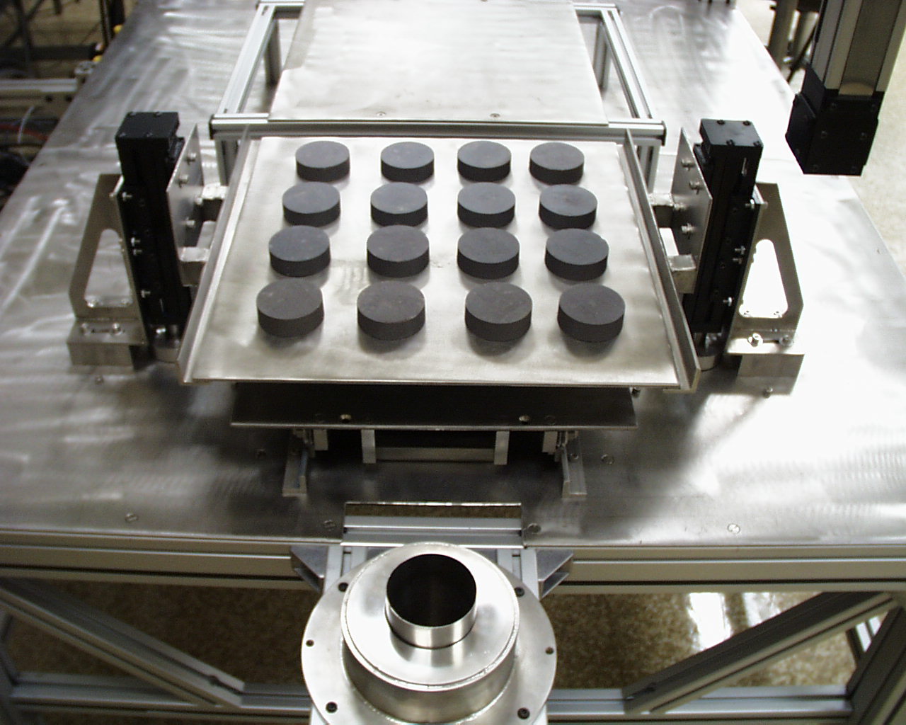
In the PIP facility, plutonium is immobilized at a nominal 9.5-weight percent concentration within titanate-based ceramic forms called pucks. Once fabricated, pucks are transported in batches to an area of the PIP facility where they will be loaded into cans. This area is called the "Can Loading" glovebox and is described in detail by Kriikku, et.al. [3]. The major equipment in this glovebox is a magnetically coupled linear transport system, a can loading robot, a helium hood, and a vision system. The linear transport system carries pucks into the can-loading glovebox on a "transport tray" as shown in Fig. 1. This figure shows 16 sintered pucks on transport tray. The robot, with spatial feedback from the vision system, removes pucks from the tray and places them in the can. The helium hood is used to backfill the can with helium before the can is welded shut. The opening at the top of a can is also shown in Fig. 1.
Can Loading Requirements
In actual PIP facility operations, more than 26 cans will be loaded per day. Cans will be loaded with 20 pucks each. Dimensional requirements in the can loading area make can loading a non-trivial autonomous task. The can-loading glovebox conceptual design assumes that the absolute position of individual pucks on the transfer tray is unknown. There are no engineered features to assure puck position during transport, so some shifting may occur do to vibration. In addition, the can inside diameter is 2.88 inches (73.2 mm) while the puck diameter is nominally 2.65 inches (67.3 mm), but can be as large as 2.75 inches (69.9 mm). Therefore the can loading system is designed to accommodate a 0.13-inch (3.3 mm) total diametral clearance between the puck and can. It is a system requirement that contact between the pucks and can opening be prevented during loading operations. These design objectives establish accuracy requirements for both locating pucks on the tray and loading pucks through the can opening.
Due to the radiation hazards, puck location uncertainty, and accuracy requirements, robotics provides an ideal can-loading method. In this application, a vision system is used to obtain puck location information and improve accuracy during loading.
Can Loading Robot
A prototype of the can-loading robot is shown in Fig 2. The rectangular framework supporting the robot is representative of the can-loading glovebox enclosure. The can loading robot design includes three linear axes of motion and a gripper. The first axis provides approximately 52 inches (1321 mm) of motion in the X direction, the second axis provides approximately 40 inches (1016 mm) of motion in the Y direction, and the third axis provides approximately 40 inches (1016 mm) of motion in the Z or vertical direction. A DC servomotor drives each axis and an encoder provides position feedback. An industrial computer running Windows NT â, Steeplechase â, and Citect â controls the system and provides an operator interface. The control computer also runs the pneumatic gripper and vacuum system. The gripper is designed to grab 3-inch (76.2 mm) outside diameter (OD) cylindrical objects. This allows the gripper to hold can stubs, reject cans, and an assortment of tooling. The puck-lifting tool is made-up of three parts, a suction cup, a 40-inch (1016 mm) hollow pipe, and a 3-inch (76.2 mm) OD lifting fixture. The suction cup allows the tool to lift the pucks from their top surfaces. The suction cup also provides some compliance due to the flexible cup material. This is an advantage since the total puck to can clearance is approximately 0.13 inches (3.3 mm). The vacuum line runs up the hollow pipe to a fitting on the lifting fixture. The mating fitting is on the gripper and the two are joined when the gripper closes on the tool-lifting fixture. The lifting fixture is 3 inches (76.2 mm) in diameter where it makes contact with the robot’s gripper, and it has a larger diameter (or flange) above and below. These flanges prevent the tool from moving when the gripper is closed on the tool.
The can-loading robot is capable of moving all three axes with a 30-pound load while maintaining repeatability of each axis to +/- 0.01-inch (+/- 0.25 mm). Axis travel speeds are rated at 12-inches (305 mm) per second, however, at the expected PIP facility puck production rates, the robot will operate at a fraction of this speed.
Can Loading Vision System
A vision system was designed to provide the can-loading robot with puck locations on the transfer tray, and to assist in puck alignment immediately prior to can loading. The vision system design includes two standard grayscale Charged Coupled Device (CCD) cameras (640 x 480, 8-bit, RS-170 output) connected to a Matrox Pulsar â video frame grabber in a Dell â 333 MHz computer. The PC’s operating system was Windows 98 â, and image processing was performed using custom software written in Microsoft Visual C++ â. A serial provided communications between the vision system computer and the robot control computer.
Vision System Operation
The first vision system camera is located above the robot (as shown in Fig. 2, "Camera-1"). Camera-1 has a field-of-view that is slightly larger than a transfer tray. The vision system uses images from camera-1 to locate all pucks on a transfer tray simultaneously. Fig. 3 shows a typical processed image from camera-1. This figure was taken from the vision system computer screen, and shows that all pucks have been located in the scene. Outline and center markings are superimposed by the image processing software to indicate successful puck identification. Using the 333Mhz PC and custom C++ image processing software, the image shown in Fig. 3 is updated 15 times per second. The data generated from this processed image obtains ‘coarse’ puck locations (i.e. +/- 0.125 inches (3.18 mm)). This level of accuracy is sufficient to position a 2-inch (51 mm) suction cup near the center of a 2.65-inch (67.3 mm) puck. Camera-1 image coordinates are related to robot coordinates using a vision system calibration step.
The second vision system camera is located roughly 8 inches (203.2 mm) from the can, and is positioned below the floor level of the glovebox. This camera is ‘upward-looking’ and is used to obtain high-accuracy puck location with respect to the robot suction cup center. Once the robot receives the puck location (using camera-1), it picks the puck up, and positions it over camera 2. Camera-2’s field-of-view is slightly larger than a single puck, and a typical image taken with this camera is shown in Fig. 4. Puck location is established within +/- 0.008-inch (0.2 mm) in this scene. The vision system measures the offset between the puck center and the suction cup center (Fig. 4a), and instructs the robot to adjust its position to make-up the offset (Fig. 4b). The crosshairs in Fig. 4 represent suction cup center location, which is established during a vision system calibration step.
Vision System Calibration
Spatial calibrations are performed with both cameras to relate vision system coordinates to robot coordinates. Vision system coordinates are represented by a 2-D Cartesian system in ‘pixel’ units. A pixel represents the smallest discrete image element (e.g. the images acquired with this system are 640 x 480 pixels in size). Robot coordinates are represented by a 2-D Cartesian system in ‘count’ units. A ‘count’ is a minimal discernable value generated by position encoding devices in the robot’s linear drives (e.g. the drives in this application generate 26,641 counts per inch).
The calibration for Camera-1 relates image scene 2-D Cartesian coordinates to robot 2-D Cartesian coordinates. A manual calibration procedure was used to establish this relationship. Pucks were placed on the transfer tray at given robot x-y locations, and the robot coordinate pairs were recorded. An image was acquired of the pucks on the tray, and the puck centers were located by the vision system relative to the image scene. This yielded a set of vision system coordinate pairs. The robot coordinates and corresponding image scene coordinates were used to derive a set of second-order polynomial calibration equations of the form:
X’ = C1X2 + C2X + C3 (1)
Y’ = C4Y2 + C5Y + C6 (2)
where:
X & Y represent image coordinates (pixels)
X’&Y’ represent robot coordinates (counts)
Ci are calibration constants
NOTE: This calibration method assumes that the x transformation is independent of y (and vise versa). This assumption can introduce significant error, especially if optical parallax is an issue. In this application the above calibration yields acceptable results, and is used for simplicity.
Camera-2 is responsible for determining the location of a single puck with respect to the robot suction cup. There are two parts to this calibration. First, the robot presents an ‘empty’ suction cup (i.e. no puck attached) to Camera-2. While monitoring the output of camera-2, the robot is moved to position the suction cup close to the image center. Robot coordinates (X’c, Y’c) and image coordinate (Xc, Yc) are recorded at this point. Again, image coordinates are recorded in ‘pixels,’ and robot coordinates are recorded in ‘counts.’ The crosshairs in Fig. 4 intersect at (Xc, Yc).
The second part of camera-2’s calibration is similar to the calibration performed for camera-1. Recall that the vision system will measure the offset between the puck center and the suction cup center and instruct the robot to adjust its position. Therefore, a constant is sought which defines (number of robot counts to move) per (number of pixels offset measured). This constant is defined in a calibration step as follows: While monitoring the output of camera-2, the robot is moved to get robot coordinates defining the image boundaries. The robot is moved such that the center of the suction cup is at the leftmost boundary of the image, and the robot x coordinate (i.e. X’min) is recorded. This procedure is repeated at the remaining boundaries to get X’max, Y’min, and Y’max. These values are used in the following equations that define the adjustment required to align the puck center and suction cup center:
DX’ = (Xpc– Xc) * (X’max – X’min)/640 (3)
DY’ = (Ypc– Yc) * (Y’max – Y’min)/480 (4)
where:
DX’, DY’ defines robot offset movement required (counts)
Xpc, Ypc defines puck center location per image analysis (pixels)
Xc, Yc defines suction cup location (pixels)
X’max is the robot coordinate at rightmost image boundary (counts)
X’min is the robot coordinates at leftmost image boundary (counts)
X’max is the robot coordinate at bottom image boundary (counts)
X’min is the robot coordinates at top image boundary (counts)
NOTE: Again, this is a simple calibration ignoring certain dependencies and secondary effects. A simple calibration was chosen in conjunction with a recursive feedback algorithm (i.e. measure, move, re-measure, move, etc.). Since the equations above represent the dominant factor in this application, they provide acceptable results, however these equations can lead to significant error in many applications.
Image Processing Theory
The following discussion applies to both camera-1 and camera-2 output. Images acquired in this vision system are 8-bit grayscale (i.e. 256 shades of gray) 640 pixels wide and 480 pixels high. As is the case with most image processing algorithms, a feature enhancement technique is used to distinguish salient features from the background. A key advantage in this particular application is that the items-of-interest are pucks (which are very dark gray), and they are always set against a light background. This sharp contrast permitted the use of simple binary thresholding as the feature extraction technique. With binary thresholding, a threshold gray shade is selected (between 0 and 255), above which all pixel intensities are forced to white, and below which all pixel intensities are forced to black (yielding a binary image). A thresholding algorithm takes on the following form:
Let: Ixy = gray shade intensity at pixel location x,y
IT = selected threshold intensity
For all Ixy >= IT , Ixy = 255 (white)
For all Ixy < IT , Ixy = 0 (black)
An example of image thresholding is shown in Figs. 5a and 5b. Figure 5a is a typical grayscale image of pucks on the transfer tray captured from camera-1. Figure 5b is the same figure after applying a binary thresholding with a threshold value (IT=162).
After applying the thresholding algorithm, the large features in the image (Fig. 5b) represent pucks. The next step is to determine area and center locations of each puck Area is calculated by summing all adjacent pixels which make-up the puck. Centers are obtained by determining puck centroid location. The following equations were used to calculate area and centroid location.
A=S[Dai] (5)
Xbar= S[XiDai]/A (6)
Ybar=S[YiDai]/A (7)
where:
A is the puck area in pixel units
Xbar, Ybar define the area centroid location of the puck
Dai individual pixel area (Dai =1 pixel)
Xi, Yi the coordinate of the pixel Dai
Once puck centroid locations are determined, values for Xbar and Ybar are substituted in equations (1) and (2) respectively to yield robot coordinates for the puck (X’, Y’).
Vision System Communications with Robot
In this application there is a robot control computer and a separate vision system computer. The robot computer is the supervisory system and the vision system responds to robot commands. The communication link between the robot and the vision system is a serial (RS-232) link. The messages between the systems are simple ASCII strings and Table 1 shows sample messages and describes each message.
Table 1 – Sample Vision System/Robot Communication Messages
|
Message |
Description |
|
Robot> Hello |
Robot is checking to see if vision system is active |
|
Vision> Puck |
Vision system is alive and found a puck |
|
Robot> Send X position |
Robot wants X’ coordinate for a puck |
|
Vision> 123000 |
Vision system responds |
|
Robot> Send Y position |
Robot wants Y’ coordinate for a puck |
|
Vision> -50000 |
Vision system responds |
|
Robot> Done |
Robot has loaded the puck and is ready |
|
Vision> Stop |
Vision system can’t locate any more pucks |
Results
The vision system described herein works well for can loading operations. Camera-1 locates pucks with sufficient accuracy to guide the robot to the desired puck and engage the suction cup. The vision system locates up to 32 pucks simultaneously, and these can be arranged in any fashion on the transfer tray. Exception handling has not been implemented for stacked pucks, broken pucks, and/or touching pucks. While these issues are within the bounds of machine vision technology, they are beyond the development and test program scope outlined by the DOE. Later phases of facility design will thoroughly address these details.
After picking-up a puck, the robot presents the puck to camera-2. Here, the offset between puck center and suction cup center is measured (Fig. 4a), and the robot position is corrected to move the puck center to the suction cup center location (Fig. 4b). This correction is applied when the robot is instructed to move to the pre-programmed can centerline position. Uncorrected, the robot would align the suction cup with the can centerline. Using camera-2’s correction, the robot aligns the puck with the can centerline. This procedure works well for the can-loading application tolerances.
To date, over 100 can-loading tests have been conducted. In these tests, various quantities of pucks were loaded from arbitrary transfer tray positions. The system performed well in all cases.
Conclusions
A vision system was developed in support of the U.S. Department of Energy - Plutonium Immobilization Project. This system provides visual feedback to a can-loading robot that places plutonium/ceramic pucks in stainless steel cans. Inexpensive grayscale CCD cameras were used in conjunction with an off-the-shelf video capture card and computer to build an effective two-camera vision system. Testing demonstrates the viability of this technology for use in the Plutonium Immobilization Project facility, which is scheduled to begin operations in 2008.
References:
Figure 1. Transfer tray with 16 pucks.
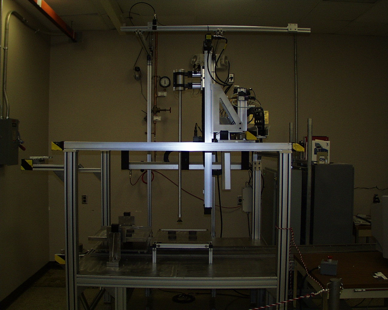
Figure 2. Can loading robot
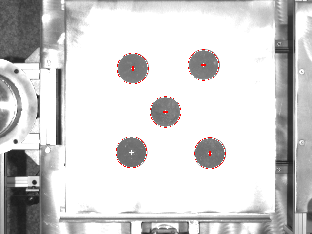
Figure 3. Typical processed image from robot vision system camera-1.
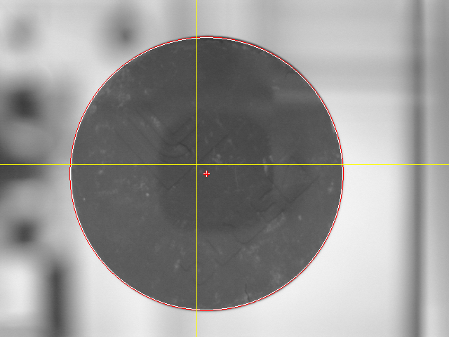
Figure 4a. Camera-2 image before correction is applied. Shows slight misalignment of puck center and suction cup center.
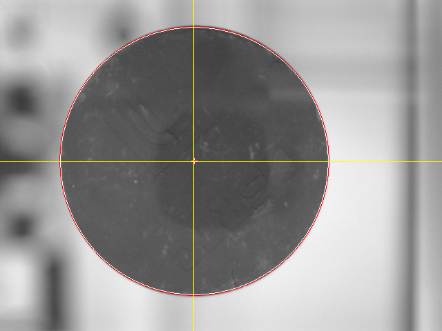
Figure 4b. Camera-2 image after correction is applied.
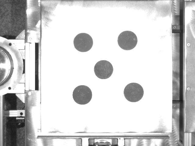
Figure 5a. Typical 256 shade (8-bit) grayscale image before thresholding is applied.
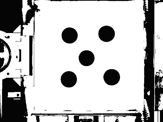
Figure 5b. Grayscale image after thresholding (IT=162).