This report was prepared as an account of work sponsored by an agency of the United States Government. Neither the United States Government nor any agency thereof, nor any of their employees, makes any warranty, express or implied, or assumes any legal liability or responsibility for the accuracy, completeness, or usefulness of any information, apparatus, product or process disclosed, or represents that its use would not infringe privately owned rights. Reference herein to any specific commercial product, process or service by trade name, trademark, manufacturer, or otherwise does not necessarily constitute or imply its endorsement, recommendation, or favoring by the United States Government or any agency thereof. The views and opinions of authors expressed herein do not necessarily state or reflect those of the United States Government or any agency thereof.
This report has been reproduced directly from the best available copy.
Available to DOE and DOE Contractors from the Office of Scientific and Technical Information, P. O. Box 62 Oak Ridge, TN 37831; prices available from (423) 576-8401.
Available to the public from the National Technical Information
Service, U.S. Department of Commerce, 5285 Port Royal Road, Springfield, VA
22161.
Since about 1940, many types of ion exchange resins have been produced and
studied. This paper specifically addresses the use and life cycle of ion
exchange resins as they relate to the SRS Spent Nuclear Fuel Storage Basins.
In the very early sixties, the Savannah River Site (SRS) began using ion exchange resins in the 100-Areas (Reactor Disassembly Basins) and at the Receiving Basin for Offsite Fuels (RBOF) for basin water chemistry and corrosion control of stored spent nuclear fuels (SNFs). This paper chronicles the use of two (2) types of ion exchange resins and their affect on basin water quality from the sixties until today.
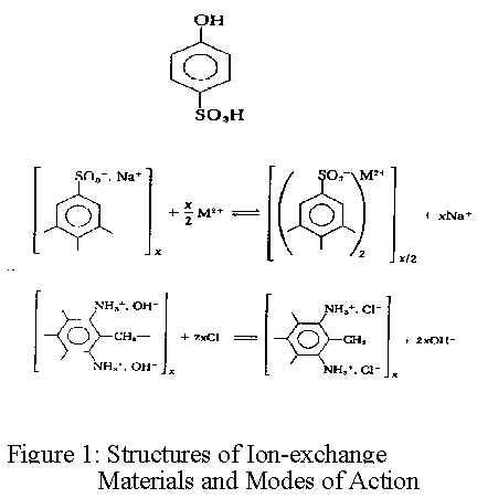
The two (2) types of ion exchange resins that are used at SRS for basin chemistry control are:
Ref: figure 1, Structures of ion-exchange materials and modes of action

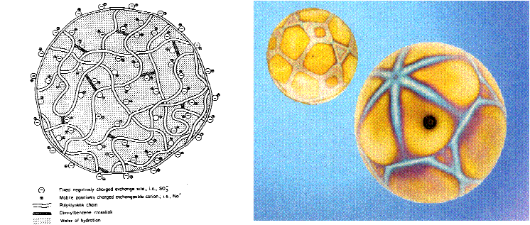
Ion exchange resins are based on a styrene polymer crosslinked with divinyl benzene. The long chains of polystyrene are held together in a spherical bead by the crosslinking agent. An analogy that has been used by some to describe this structure is a ball of spaghetti which has cooled to the point where the individual strands have become glued or cemented together because of soluble starches. The cementation corresponds to crosslinkage. These polymers are functionalized to make cation and anion exchange resins. The functional groups attached to the polymer are hydrophilic and draw water into the polymer matrix swelling it until the polymer strands can swell no more. The resulting water inside the ion exchange resin is referred to as the chemical moisture. The amount of water that can be held by any given resin is called the moisture holding capacity. This moisture holding capacity is related to the size of the resin bead. For both ion exchange resins, the effective size is approximately 0.50mm. The polymer chains, crosslinks, water of hydration, fixed ion exchange sites, and mobile exchangeable ions are shown in figure 2.
Ion exchange is the process in which ions, held by electrostatic forces to charged functional groups on the surface of an ion exchange resin, are exchanged for ions of similar charge from the solution in which the resin is immersed. The chemistry involved in the ion exchange process can be illustrated as follows (see figure 3):

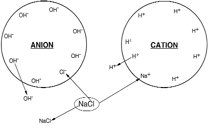
When ion exchange occurs, the cations or the anions in the solution are interchanged for those in the exchanger, but both the solution and the exchanger remain in a condition of electroneutrality. In the case of a cation exchanger, for example, one calcium cation which has two positive charges (Ca2+) when it leaves the water, must replace in the exchanger two hydrogen cations, which each have a single positive charge (2H+).
When an ion exchange resin loses its exchange capacity, the resin must be regenerated. Regeneration consists of passing a chemical solution through the exchanger, resin vessel or tank and exchanging or replacing ions removed from the wastestream with ions that can later be exchanged with metals from wastestreams. Ion exchange resins must be cleaned when they occasionally become clogged or fouled. At SRS, it is common practice to perform external regeneration, which occurs in external vessels to which the exchanger is sluiced out of portable deionizers after exhaustion. The regenerative media used are:
With regard to storage, ion exchange resins are produced and sold as moist
beads which contain approximately 40% water by weight. They are stored and
shipped in sealed polyethylene lined containers which aid in their shelf-life
preservation. At SRS, stored virgin resins are housed in temperature
controlled warehouses until needed. Storage temperatures are maintained from
40°F to 100°F to avoid resin degradation. Typical shelf life under
proper storage conditions is two years for Anion resin and five years for
cation resins. It should be noted here that these are what should be expected
as a minimum shelf-life for virgin resin with proper storage. Resins stored
beyond the typical shelf-life should be analyzed prior to use.
During long periods of storage, ion exchange resin can experience problems that
can render them inoperable or to a lesser extent degraded to the point of
reduced performance. A listing and description of some of these problems
are:
Freeze-Thaw Cycles: Ion exchange resin contains approximately 40% water by
weight when drained. This is the chemical moisture which was addressed
earlier. When a resin undergoes freezing temperatures, the water inside
expands as it becomes solid thereby stretching the resin polymer. While ion
exchange resins are fairly strong materials, and a single freezing cycle is
unlikely to fracture the resin beads, repeated cycles of freezing - thawing
(expand-contract) often leads to broken polymer bonds and physical breakdown of
the resin with subsequent degraded performance and increased resin fines.
Drying: Since ion exchange resins contain a considerable amount of water
inside their polymer structure, water evaporation or drying will cause the
resin to contract or shrink. Shrinking is not a problem for the resin,
however, when rehydrated the resin expands (swell) rapidly to accommodate the
water of hydration. This rapid expansion can cause the polymer strands to
break, which causes the resin bead to break. The same operational and
performance problems resulting from bead breakage due to freeze-thaw cycles can
be experienced from the rehydration of dried resin.
Biological Growth: When an ion exchange resin is in use, it is exposed to
naturely occurring organics and bacteria from new raw waters. Both the organic
matter and the bacteria tend to concentrate on the resin. Repeated
regenerations aid greatly in keeping the concentration of bacteria and organics
relatively low. When the resins are used and stored for extended periods
(inactive) and not regenerated, bacteria can multiply, feeding on the organic
matter held by the resin. If the resins are not cleaned prior to storage
(lay-up), a foul smelling brew of bio-slime can grow. While this can sometimes
be cleaned off the resin, it can not only be expensive and time consuming, but
an unpleasant task with no guarantee of positive results.
Chemical Decomposition: The functional or exchange groups chemically attached
to the resin polymer to make anion exchange resins are susceptible to
degradation through various chemical reactions. The strongly basic anion
exchange resins are used to remove silica from water and are therefore
subjected to fouling. When concentrations of silica within the resin are high
enough, the silica starts to slowly polymerize, making larger molecules of
silica which are difficult to remove from the resin and can block the transport
of ions into and out of the resin, thereby reducing its operating capacity.
Frequent regenerations with heated NaOH will remove much of the silica from the
resins and do not allow significant silica polymerization to occur. If silica
is allowed to concentrate and remain in a resin during long lay-up periods, a
hot caustic soak to depolymerize and remove this silica will be required prior
to recommissioning. It is important to note here, that a hot caustic soak can
slightly degrade the resin chemically.
In addition to removing and concentrating ions such as sulfate
(SO4=), chloride (Cl-) and silica
(SiO2), anion exchange resins will remove organics from water.
Styrenic resins do not give up organics readily, which leads to organic fouling
and loss of resin performance. This is usually characterized by low operating
capacity, long anion rinses and low pH effluent. Most naturally occurring
organics are large humic and fulvic acid species which take a long time to
diffuse in and out of the resin. If organic matter is on the resin prior to
storage, the long storage period will allow the organics to penetrate deep into
the resin polymer making it very difficult, if not impossible to remove. If
this condition is severe enough, organic fouling characteristics will be
experienced upon recommissioning of the resin and poor performance will be the
result.
Cation exchange resins selectively remove and concentrate cations such as
sodium, calcium and magnesium ions. Calcium and magnesium ions can form
insoluble precipitates with sulfate (SO4=) and hydroxide
(OH-) ions, respectively. Storage of unregenerated cation resin in
a sulfuric acid or sodium hydroxide solution could lead to a precipitate
forming within the resin bead which, once formed, is extremely difficult to
remove. The result would be poor cation capacity due to the precipitate
blocking the flow of ions to the exchange sites and high hardness leakage from
slowly dissolving calcium sulfate (CaSO4) or magnesium hydroxide
(Mg(OH)2) precipitates.
Note: The discussion on how spent ion exchange resins have been taken out of service (Decommissioned) and packaged for disposal at SRS will be addressed later in this paper.
The role of ion exchange resins in long-term spent fuel storage starts with the
condition of the storage basins, i.e., water quality. The chemical parameters
of the basin waters and the water's effect on stored spent fuel have a direct
effect on the fuel with regard to corrosion, biological growth and radionuclide
activity. The control of pH, conductivity, cesium 137 (Cs137) and turbidity
are the parameters that will be expounded upon as part of the evolution of the
SRS experience with ion exchange resins and basin clean-up. For the purpose of
this paper, the 100 L-Area Disassembly Basin at SRS will be used for the basin
clean-up discussion as L-Basin is representative.
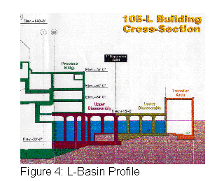
The L-Disassembly Basin contains 3.5 million gallons of water. Currently, there are approximately 1,000 spent fuel assemblies stored in the L-Basin. In 1995, SRS was asked by the Department of Energy to create additional spent fuel storage space as the RBOF storage facility was rapidly filling up with fuel. To facilitate the need for expanded fuel storage space the entire reactor fuel disassembly basin was converted to a fuel storage facility. The L-Disassembly basin was made "fuel ready" with the application of ion exchange resins and updated service equipment. See Figure 4, L-Basin Profile below.
With a continued increase of spent fuel being stored in the basin came an
increased need to become more efficient at the business of deionizing basin
water with ion exchange media. Samples of basin waters were taken at a greater
frequency to assess what was in the water in the form of chemical constituents
and radionuclide activity.
Based on the analytical data on water chemistry, it was determined that, (1)
filtering the basin water through sand would only trap particulate matter at a
10 micron level and (2) using a portable deionizer at 120gpm would not deionize
the basin water to a level whereby conductivity and pH would be greatly
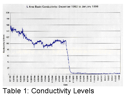
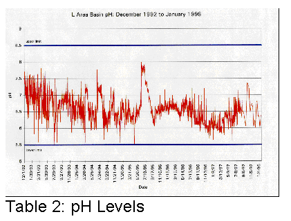
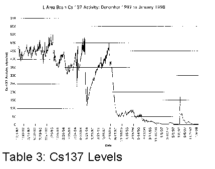
affected. Tables 1, 2 and 3 illustrate graphically where conductivity, pH and
Cs137 levels were with only sand filters and portable deionizers.
It became clear that something different had to be done if the basin water was to be cleaned up more efficiently.
In the summer of 1995, SRS subcontracted the cleanup of the L-Basin. The
subcontractor brought in both ion exchange media, filters and deionizers to
accomplish the task. As the ion exchange resins became spent, they were not to
be regenerated but packaged for disposal. In the fall of 1995, the
subcontractor had fulfilled the task of the basin cleanup. It was at that time
that SRS initiated a project called the Disassembly Basin Upgrade Project (DBU)
that was designed to maintain basin water quality to levels that would inhibit
fuel corrosion and enhance long-term fuel storage. The DBU Project featured
continuous deionizing and filtration of the basin water. Today, the water in
the SNF storage basins at SRS is near pristine, as can be seen by the water
clarity and the near absence of ionized materials and reduced radionuclide
activity.
With the SNF basins clean and with good corrosion control, attention had to be placed on the long-term disposal of the ion exchange resins that had been used in the long and continued campaign of cleaning basin waters and maintaining good water quality. To do this, 144,000 pounds of spent resin had to be decommissioned (taken out of service), characterized, packaged and permanently disposed of.
The decommissioning phase involved taking representative samples of the spent
resin for radiological assessments. If the resin's radiological dose rate
exceeded the limits for the disposal package, then regeneration of the spent
resin would be necessary before characterization, packaging and disposal could
commence. From the radiological assessment performed, none of the 144,000
pounds of spent resin exceeded the limits of the proposed disposal packages.
During the resin characterization phase, the resins were analyzed for both
chemical and radiological parameters to ensure that they would fit the
packaging envelope that had been selected and that the limits for disposal were
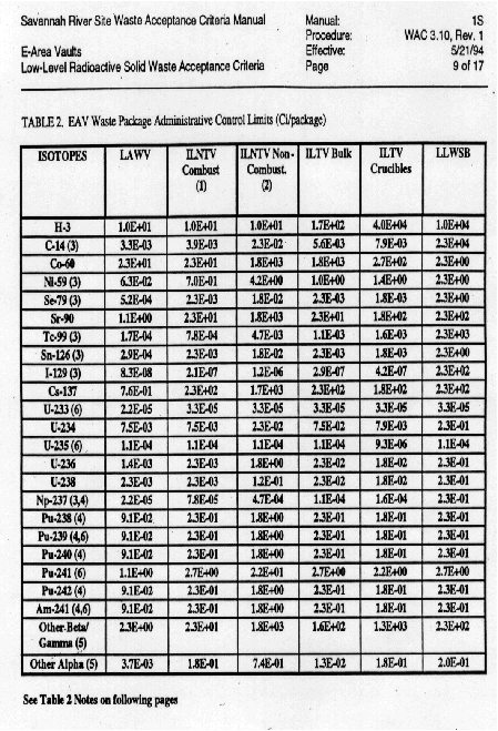
in concert with WAC 3.10, Rev. 1. Waste Acceptance Criteria for E-Area Vaults
(Ref. Table 4).
From the analytical results, it was found that the resins met the requirements of both the packaging envelope and the waste acceptance criteria for the E-Area Vaults. Additionally, radiological surveys on the packaged resins yielded <=50 Mrem/hr on the package contact.
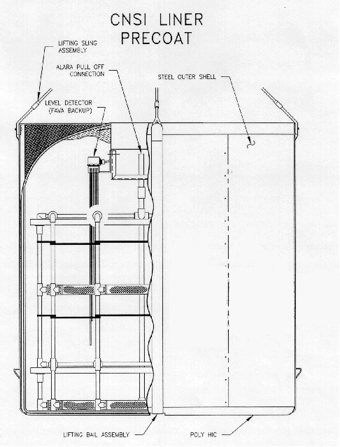
For spent resin containment, drying and disposal, SRS employed the use of High Integrity Containers (HICs). These containers are certified by the State of South Carolina for long-term containment of depleted resin systems (see figure 5 - Typical Polymer HIC).
HICs are fabricated using a high density, cross-linked polyethylene matrix.
This matrix offers strength, durability, radiation resistance and chemical
resistance for storage or disposal life in excess of 300 years. The
polyethylene matrix also contains an ultraviolet inhibitor and when used in
conjunction with inside storage and/or covering with opaque material for
storage, it eliminates the effects of the exposure to sunlight. The outer
shell of the HIC consists of ¼" carbon steel which adds to the strength of
the container.
The following parameters govern the container (HIC).
The principal of operation to de-water a HIC friend with depleted resins to
less than 1% free water is:
After loading, a dewatering pump is connected to the HIC's dewatering hose.
The effluent is routed to a desired location, the pump is started and allowed
to operate for eight cumulative hours. The pump must be capable of pulling a
vacuum of 10 inches to 15 inches of mercury. Upon completion of eight hours
cumulative run time, the pump is stopped and the container (HIC) is allowed to
settle for twelve hours. This process is repeated once more. A verification
bottle <= 1000 ml is connected to the water discharge line and the vacuum
pump is started and allowed to run for four (4) hours. If the verification
bottle has > 1000 ml of liquid after four hours, the vacuuming process is
repeated and the HIC allowed to stand for eight hours. Finally, the sampling
process is repeated. With the above de-watering procedure completed,
reasonable assurance that less than 1% free standing water by volume is present
in the container. For acceptance, all of the de-watering steps must have been
satisfactorily completed without abnormalities.
From the characterization and packaging phases of the spent resins, it was
determined that the final resting place for the 12 HICs containing 144,000 lbs
of spent resin would be at E-Area's intermediate level vaults.
On September 12, 1997, SRS satisfactorily completed the shipment of the spent resins to the E-Area Vaults, their final resting place.