Application
of the Systems Engineering Approach
to the Tritium Extraction Facility Design
P Simpkins
Westinghouse Savannah River Company
Aiken SC, 29808
Abstract
The Commercial Light Water Reactor - Tritium Extraction Facility is being designed and built as a tritium processing facility at the Savannah River Site (SRS) in South Carolina. When built it will be the only facility processing tritium in the United States. The design of this facility required some equipment to be designed as one of a kind. The Systems Engineering (SE) approach was applied to define the functions and requirements necessary to design and operate the facility. The SE approach for the Tritium Extraction Facility (TEF) was a major effort encompassing Requirements Analysis, Risk Management, Interface Control, and supporting plans and documentation for the facility and 23 major systems. This paper will describe the SE approach in general and give examples of selected Functions and Requirements (F&Rs) supporting the TEF design. Also presented will be advantages of using the SE approach on the design of the TEF and observations made during the design process.
Introduction
The Systems Engineering (SE) approach at the Savannah River Site (SRS) has been developed through the partnering with industry leaders and site applications. The Tritium Extraction Facility (TEF) was one of the first detailed efforts at the SRS which encompassed all the aspects of the SE approach. This paper will present an example that begins with the upper tier functions in the Facility Design Description (FDD) and traces the Functions and Requirements (F&Rs) through the System Design Descriptions (SDD) to the component requirements. The last step in the SE approach is Validation and Verification of the requirements. To accomplish this step the TEF design effort decided to develop a traceability matrix that correlated the requirement to a specific design output document. An example of the matrix will be shown later.
The SE approach was applied at the beginning of pre-conceptual design and continues to this day during the construction phase of the project. The FDDs, SDDs and baseline documents are updated on a regular basis as the design and construction progresses.
SDDs
Because of the large size of the TEF project, the facility was broken up into 23 major systems; each system was defined and described in an SDD. The following are the 23 systems that support the design and the FDD.
- Receiving, Handling and Storage Systems
- Tritium Extraction Systems
- Product and Flush Gas Evacuation System
- Tritium Recovery System
- HP and Radiometric Laboratory System
- Mass Spectrometry and Accountability Systems
- Solid Waste Management System (SWMS)
- Radiation & Contamination Sampling/Monitoring Systems
- Process Confinement and Clean-up System
- Electrical Power Supply Systems
- Storm Sewer System
- Domestic Water Supply System
- Sanitary Waste Water System
- Process Waste Water System
- Process and Building Chilled Water Systems
- Inert Gas System
- Plant and Breathing Air Systems
- Heating, Ventilation, and Air Conditioning (HVAC) System
- TEF Building and Cell Structures System
- TEF Support Facilities System
- Integrated Control System
- Plant Communication System
- Fire Protection System
Location
The location of the TEF is important to define because it determines design constraints (requirements) that will be imposed on the facility. The TEF will be located at the SRS which is a 300 square mile reserve located on the south side of South Carolina along the Savannah River near Augusta, Georgia. The TEF will be placed in the tritium area due to its already established tritium capabilities. The facilities in tritium area will further process the tritium product before it is determined as usable.
Definitions
The following definitions will help in the discussion of the TEF design that follow:
- Tritium Producing Burnable Absorber Rods (TPBARs)
- TPBARs are pencil thin 12 foot rods that capture the tritium being produced at the reactor.
- Consolidation Container
- The container utilized for shipment of the TPBARs in the transport shipping cask. They are also used in the operation of the TEF through waste disposal. The TPBARs are loaded in the Consolidation Container at the reactor facility.
- Extraction Basket
- The container for the TPBARs throughout the preparation, extraction, and post extraction process at the TEF. The extraction basket with a Consolidation Container is placed in the waste overpack when extraction is complete.
- Overpack
- The waste container into which the extraction basket and other waste is placed prior to shipment to the waste disposal area.
- Modules
- A secondary confinement structure that houses equipment for preparation, extraction and storage of TPBARs during all normal, abnormal and infrequent operations.
Systems Engineering Approach
The SE approach used at Westinghouse Savannah River Company incorporates customer input to formulate the problem solution. Figure 1 shows a visual perspective of the SE approach.
The SE approach envelopes four major steps. These step are 1. Mission Definition and Analysis, 2. F&Rs Analysis and Allocation, 3. Alternative Solutions Evaluation and Selection, and 4. Validation and Verification. Throughout these steps the project also applies Technical Integration, Interface Control, and Risk Management.
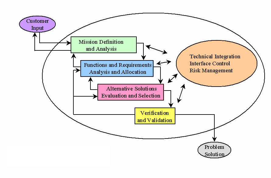
Figure 1. System Engineering
Approach
Mission Definition and Analysis
In order to develop adequate requirements, the mission and objectives need to be defined so that the requirements can be validated. This validation shows that the requirements meet the intent of what the facility was designed to accomplish. A key part ot the SE approach was being involved early in the design to help establish the overall mission and F&Rs for the Commercial Light Water Reactor (CLWR) Program and not just the TEF. The primary mission for the CLWR Program is:
"The CLWR Program will develop, by 2003, the production capability and operation systems necessary to produce tritium in a commercial reactor so that tritium can be delivered to the nuclear weapons stockpile."
In support of the project mission, the primary mission for the TEF project is:
" to extract tritium from tritium producing burnable absorber rods that have been irradiated in a commercial light water reactor, and to deliver tritium-containing gas to SRS Facility 233-H."
The objectives of the TEF were defined by the customer, Department of Energy, and have been incorporated into the FDD upper level functions. These are presented in the next section.
F&R Analysis and Allocation
The F&R analysis involves the breaking down of functions into a hierarchy of functions and sub-functions until discrete tasks can be defined and related to mission originating requirements. Functions and sub-functions are allocated to the systems, structures, and components. Also as part of this step; 1) performance requirements are identified and allocated to functions, 2) design constraints are allocated to systems, structures, and components, and 3) interface requirements are identified for system to system interfaces. External interfaces to the facility are a major input to this step.
Upper Level Functions
Once the mission is defined for the facility, functions are developed and captured in the FDD document. The top facility level functions and the customer objectives for the TEF are:
F.FDD.0.0 Safely extract tritium-containing gases from irradiated TPBARs and transfer gas to current tritium processing facilities to meet Department of Energy requirements.
F.FDD.1.0 Minimize releases of radiological and chemical hazards to the environment, minimize personnel exposure, and apply As Low As Reasonably Achievable concepts.
F.FDD.2.0 Receive incoming tritium sources and prepare for the extraction and processing of tritium.
F.FDD.3.0 Handle empty shipping casks.
F.FDD.4.0 Extract tritium containing gas for processing from irradiated TPBARs while minimizing releases.
F.FDD.5.0 Recover tritium from process gases and waste gases and transfer tritium containing gas to current tritium processing facilities.
F.FDD.6.0 Manage the types and quantities of waste generated in preparation for final disposition.
F.FDD.7.0 Provide integrated support for tritium process performance and accountability to maintain tritium production and safe operation during all modes of the TEF operation.
F.FDD.8.0 Provide integrated plant monitoring and controls for production and support systems during all modes of the TEF operation to support tritium production and safe facility operation.
Alternative Solutions & Evaluations and Selections
Alternatives to the design were discussed during pre-conceptual design. The selected overall facility design was documented in the conceptual design report. During final design many studies were also conducted to formulate alternative designs of the components.
By understanding the requirements of the equipment and components being designed, these studies helped drive a better selection of solutions to the defined requirements. Three examples of developing a better design are:
Transporter
The transporter was removed from the design early due to identification of problems with operability. As part of a risk handling strategy, development work on the transporter and establishment of a vender interface were completed at the beginning of the design process. The result was the early identification of operational problems and the ability to find an alternative solution.
The risk was a tritium release due to possible TPBAR failure. The transporter was conceptualized to be a leak-tight, inerted box that would transport the TPBARs from module to module. Each operational process done at the TEF was completed in a module so that any escaping tritium gas would be contained in a secondary confinement area and the spread of contamination would be minimized. The TPBARs were thought to require a secondary confinement at all times even during transportation between the defined modules of storage, TPBAR preparation, furnace extraction, and disposal.
No fabricators for the transporter were able to obtain the leak rate requirement of less than 1 x 10⁻⁶ std-cc/sec Helium with a positive pressure differential of 2-1/2 inches of water column. Due to vendor knowledge and testing the transporter was not able to be built.
However, due to early identification of the problem another solution was developed and evaluated. To resolve the risk of TPBAR failure, the design progressed to using a desiccant (a moisture absorbing material) in lieu of inerting gas in the TPBAR basket. Because of this design evolution, the transporter was removed from the design.
Robotic Crane
A precise robotic crane was conceptualized to move the extraction baskets to the individual modules within the Remote Handling Area. (The Remote Handling Area is the inner cell portion of the remote handling building of TEF where remote processing occurs.)
After implementing the risk strategy of early discussions with vendors and internal reviews to determine the feasibility of a robotic crane, the project decided to proceed with a standard remote crane and provide a moveable platform mounted robot. This specialized robot could perform the precise manipulations required for TEF maintenance. The standard remote crane would handle normal operations. This alternative reduced the risk of remote operations and remote maintenance, thus providing a less expensive solution for TEF needs.
Storage Area
The storage area for extraction baskets and overpacks was initially designed to allow access to the stored extraction baskets using the transporter. When the transporter was removed from the design, the circular access holes in the storage areas top shielding plates were to small to allow the Remote Handling Area Cranes grapple and cables to fit down in the hole to pick up the basket. This interfacing problem was discovered during a crane study because of well known requirements and parameters of the Remote Handling Area Crane and storage areas.
The access holes could not just be made larger because of space and structural constraints. The shielding factor of the plates, that cover the storage area, also needs to be considered. The storage area needed to be covered to reduce radiation levels. Operations should only remove the minimum number of plates as possible so as to maintain as much shielding as possible. Because the requirements of the storage area for shielding, spacing, and accessibility were well defined and the constraints of the Remote Handling Area Crane for positioning and size where defined, the team found the new solution in a quick impromptu meeting. The solution was to support multiple shielding plates across the rectangular storage area with an upside-down T shaped brace. When the plate is removed it will allow access to 2 extraction basket locations and 1 overpack location which also minimizes the radiation concern.
Validation and Verification
Validation of the TEF was done to determine if the design had an adequate set of requirements to describe the function of the facility. The verification portion was accomplished by developing a traceability matrix and supported by design reviews (internal and external to the team). The matrix links all the requirements defined on TEF to a design output document, which is the solution to that requirement. These design documents can be drawings, flow diagrams, or specifications. The validation portion was accomplished by design reviews of the entire project. A team of Subject Matter Experts was formed to review the complete design at defined intervals to determine if the design met the intended mission.
Traceability Matrix
To help verification of the TEF requirements, a traceability matrix was developed for the FDD and each SDD to define each document that showed or described the designed systems, structures, and components that accomplished the associated requirement. The matrices were tables that list the requirement in its entirety and then listed the linking systems, structures, and components document in the same row. An example of this matrix is shown in Table 1, but for brevity only lists the requirement number shown in this paper and the corresponding type of documents.
Table 1. Example Traceability Matrix
|
Requirement number |
Systems, Structures, and Components Document |
|
R.FDD.2.1.a |
Drawing-1, Drawing-2 |
|
R.FDD.2.1.b |
Diagram-1, Diagram-2, Specification-1 |
|
R.RHSS.2.1.1 |
P&ID-1, Layout Drawing-1 |
|
R.RHSS.CMP.2.1.1.1 |
Specification-2, P&ID-2 |
|
R.RHSS.CMP.2.1.1.2 |
Specification-3 |
|
R.FDD.2.6.a |
Assessment-1, 2, & 3 |
|
R.FDD.2.6.b |
Layout Drawing-2, Layout Drawing-3 |
|
R.FDD.2.6.c |
Specification-4 |
|
R.RHSS.2.6.1 |
Specification-2, Specification-5, Specification-6 |
|
R.RHSS.CMP.2.6.1.1.a |
Specification-7 |
|
R.RHSS.CMP.2.6.1.1.b |
Specification-7 |
|
R.RHSS.CMP.2.6.1.1.c |
Specification-7, Study-1 |
Design Reviews
The design review team encompassed experts in Mechanical, Electrical, Chemical, and Nuclear Engineering, as well as specialties such as HVAC, criticality, safety, piping, and operations. This team of subject matter experts reviewed all the design documents developed and determined if the design met the verification requirements. Any discrepancies were fixed in the design and formally resolved by comment.
Interface Control
Interfaces interact with all the steps of the SE approach. They have the biggest impact on the F&R analysis and allocation step since defining the interfaces is vital to determining adequate requirements.
Internal Interfaces
The TEF internal system to system interfaces are described in the 23 individual SDDs. The internal interfaces were developed using interface diagrams, captured with interface requirements and managed within CORETM
External Interfaces
The external interfaces outside direct control of the facility are:
- Tritium Supply Technologies
- SRS Tritium Facilities
- SRS Infrastructures
- SRS Waste Disposal Facilities
- SRS Environment
The SRS infrastructure systems
include utility systems, logistics systems, and security/emergency response
systems. Figure 2 shows the external interfaces of the TEF in visual perspective.

Figure 2.
External Interfaces of the TEF
Risk Management
Risk management is integral to all steps of the SE approach. As part of the risk management the TEF design team identified the risk to the project, analyzed those risks, and determined risk handling strategies to reduce, mitigate or avoid the risk. The risk analyses were completed for each project phase and several intermediate parts. This helped the design team to focus their development efforts on the risk that made the biggest return on safety and cost.
Risk Analysis
The risk analysis was started during the pre-conceptual stage of the project. The risk analysis indicated the remote handling capabilities required by TEF operations were the highest risk to the facility. One of the higher risks was the remote function of breaching the TPBARs. The breaching of the TPBARs might over pressurize the module in which they were breached if the contents were released too quickly. The design team established development and prototype testing programs with the Savannah River Technology Center as handling strategies to reduce this risk. These programs were developed at the conceptual design phase to allow time and flexibility for the design to evolve.
Selected Functions & Requirements
Some examples of the F&Rs in the FDD and two of the SDDs have been chosen to trace the F&Rs from the upper tier functions to the solutions of the component requirements. Also displayed is an example of the hierarchy of the functions.
Hierarchy
The functions in the FDD were separated into hierarchies and decomposed if further definitions of the functions were needed. The functions of the FDD were then transferred to each SDD to further develop the functions to the component level. For example, the hierarchy for the upper tier function F.FDD.2.0 is represented visually in figure 3.

Figure 3. Hierarchy
for Function F.FDD.2.0
The functions were developed in the FDD as follows:
F.FDD.2.0 Receive incoming tritium sources and prepare for the extraction and processing of tritium.
F.FDD.2.1 Receive incoming tritium sources in specified delivery configurations (i.e. consolidation container in shipping casks).
F.FDD.2.2 Unload shipping casks remotely from the shipping vehicles.
F.FDD.2.3 Store TPBAR consolidation containers.
F.FDD.2.6 Remotely prepare tritium sources for the extraction process.
F.FDD.2.7 Remotely place the tritium sources into the extraction process.
Requirements
Every function has a correlating performance requirement. The tracing of the F&Rs is presented from the FDD functions, through the SDD functions, and includes the SDD requirements.
Receiving, Handling and Storage Systems
The following functions and the associated requirements for the Truck Bay Crane and the Target Rod Preparation Module have been developed in the Receiving, Handling and Storage Systems SDD.
Truck Bay Crane
The Truck Bay Crane functional tracing is as follows:
F.FDD.2.1 Receive incoming tritium sources in specified delivery configurations.
R.FDD.2.1.a The TEF shall be capable of receiving truck and rail cask shipments for each tritium delivery configuration.
R.FDD.2.1.b The TEF shall be capable of receiving a total of 14 shipments per year minimum in the configurations defined the design agency.
F.RHSS.2.1.1 Handle cask truck components.
R.RHSS.2.1.1 The truck bay lay-down area shall be capable of storing lifting yokes, and other miscellaneous cask truck devices.
F.RHSS.CMP.2.1.1.1 Disassemble cask truck from shipping cask.
R.RHSS.CMP.2.1.1.1 The shipping cask impact limiters and other protective or restraining devices shall be disassembled from the cask truck.
F.RHSS.CMP.2.1.1.2 Move cask truck components and store.
R.RHSS.CMP.2.1.1.2 The Truck Bay Crane shall be capable of moving one set of impact limiters, lifting yokes, and other miscellaneous cask truck devices.
The hierarchy of these functions is represented visually in Figure 4.

Figure 4. Hierarchy
for Function F.FDD.2.1
Target Rod Preparation Module
A select portion of the Target Rod Preparation Module functional tracing is as follows:
F.FDD.2.6 Remotely prepare tritium sources for the extraction process.
R.FDD.2.6.a The remote preparation of the tritium sources shall support the TEF extraction/processing schedule cycle. (maximum number of acceptable TPBARs per cycle time.)
R.FDD.2.6.b Remote preparation of the tritium sources shall accommodate TPBARs within a consolidation container.
R.FDD.2.6.c Each TPBAR shall be remotely breached to allow extraction of hydrogen isotopes. (location specified by design agency)
F.RHSS.2.6.1 Handle the TPBARs and extraction basket to prepare tritium source for extraction.
R.RHSS.2.6.1 The extraction basket with the TPBAR consolidation container shall be loaded into a prepared module for TPBAR extraction preparation processing without compromise to the integrity of the basket or the module.
F.RHSS.CMP.2.6.1.1 Prepare TPBARs for extraction.
R.RHSS.CMP.2.6.1.1.a All TPBARs within consolidation container shall be remotely and positively breached.
R.RHSS.CMP.2.6.1.1.b A verification of breaching shall be conducted for each TPBAR during the breaching process.
R.RHSS.CMP.2.6.1.1.c The breaching of TPBARs shall be accomplished so that the pressure increase in the module does not exceed pressure relief setting, impair or impede the module atmosphere circulation, the module stripper system(s) performance, or the modules integrity.
Figure 5 shows the design layout
of the Target Rod Preparation Module as represented in the SDD.

Figure 5. Target
Rod Preparation Module Design
Solid Waste Management System
The Solid Waste Management System (SWMS) SDD is a representation of a system that mapped a process to identify concerns early in the design, so that the individual designer can work the issues. The TEF design recognized the importance of properly storing, handling, and treating nuclear waste. Therefore, the TEF designers chose to develop an SDD specifically to define the system related to solid waste both components and work processes.
The SWMS is mostly defined as a process and not a physical system. For example the SWMS SDD defines the flow path of the expected generated waste. However, the SWMS does encompass defined components and supporting equipment such as a forklift and disposal receptacles (i.e. B-25 boxes, B-12 boxes, and 25 gallon drums).
The SWMS SDD is hierarchically tied to the FDD by the function to "Minimize radiological and chemical hazards release to the environment." The main objective of the SWMS SDD is to manage radiological and chemical hazards by implementing current site programs. The requirements of the SWMS SDD define the capability of the TEF to treat, accumulate, handle, transport, package, and minimize solid waste.
The requirements specify:
Amounts (i.e, 75 m3 (10,000 kg) ± 5 percent per year), which containers to use, and SRS Guidance Manuals for Waste Acceptance Criteria for the final disposal sites.
The SWMS relies on the Radiological Control Department to certify the waste. (Procedures defined and accomplished by operation of the facility are not defined in the requirements section).
The one component defined in the SWMS is the Overpack Cask and Trailer. These component requirements were defined because:
- It is expected to be a complex cask which has an opening in the top and bottom of the cask.
- The cask will be loaded from the top and unloaded from the bottom.
- There are shielding concerns.
Advantages of System Engineering Work on the TEF
The following are some advantages that were identified because of the use of the SE approach during the design of the TEF.
- Through implementing the risk handling strategies of testing and requirement validation, an alternative solution to the transporter was developed and evaluated during detailed design before expensive tests and prototyping was necessary.
- A precise robotic crane was conceived during conceptual design but by implementing risk handling strategies of discussions with vendors and internal reviews the risk was reduced and a less expensive alternative was found which saved design and construction cost.
- A crane study showed that due to the loss of the transporter, the storage area was found to not be functional with the crane. Well defined requirements helped drive a functional alternative quickly and inexpensively.
- By developing the SWMS SDD. The TEF design team recognized the need for a solid waste storage building early in preliminary design so that appropriate budget and schedule was allocated for the design.
- Transportation issues for solid waste were defined early so that resolution will not stall operation.
Conclusion
The SE approach successfully implemented all the aspects of defining the mission, allocating the F&Rs, determining alternative solutions, and verifying the design of the TEF. By using the SE approach the following observations were made:
- The implementation of the SE approach is helping the TEF design meet the specified mission.
- Up-front F&R analysis and risk management work to design a feasible facility.
- The TEF design team was able to design a functional solution using an adequately developed set of requirements.
- Lower cost alternative solutions were evaluated and selected to meet the requirements.
- Risks that might have created lengthy schedule delays, tremendous increased cost, or major rework to the TEF were reduced, mitigated or avoided.
- The traceability matrix simplified the technical review process
The SE approach gave a coordinated disciplined process to define the customers needs and developed a path to provide a solution to the needed requirements. The advantages of the SE approach far outweighed the cost of implementation and helped assure a functional design.
Biography
Philip Simpkins is a Senior Engineer at Westinghouse Savannah River Company with over 11 years of experience. 3 of his 6 years in SE were on the TEF project as:
- Point of Contact with design for SE.
- Developing several of the TEF SDDs.
- Developing the Interface Management Plan and Facility Acceptance Criteria.
- Leading the Risk Analysis update.
Other SE projects: 1) Pit Disassembly and Conversion Facility, 2) Central Laboratory Electrical Upgrade, and 3) Other Tritium Projects.
His previous 5 years were in Safety Analysis. He has an MS Engineering Management 91 and BS EE 89 both from the University of Missouri-Rolla.