WSRC-MS-2002-00393
Equipment Developed to Support Evaporator Operation at the Savannah River Site
Thomas A. Nance
Westinghouse Savannah River Company
Aiken, SC 29808
This report was prepared as an account of work sponsored by an agency of the United States Government. Neither the United States Government nor any agency thereof, nor any of their employees, makes any warranty, express or implied, or assumes any legal liability or responsibility for the accuracy, completeness, or usefulness of any information, apparatus, product or process disclosed, or represents that its use would not infringe privately owned rights. Reference herein to any specific commercial product, process or service by trade name, trademark, manufacturer, or otherwise does not necessarily constitute or imply its endorsement, recommendation, or favoring by the United States Government or any agency thereof. The views and opinions of authors expressed herein do not necessarily state or reflect those of the United States Government or any agency thereof.
This report has been reproduced directly from the best available copy.
Available for sale to the public, in paper, from: U.S. Department of Commerce, National Technical Information Service, 5285 Port Royal Road, Springfield, VA 22161, phone: (800) 553-6847, fax: (703) 605-6900, email: orders@ntis.fedworld.gov online ordering: http://www.ntis.gov/support/index.html
Available electronically at http://www.osti.gov/bridge
Available for a processing fee to U.S. Department of Energy and its contractors, in paper, from: U.S. Department of Energy, Office of Scientific and Technical Information, P.O. Box 62, Oak Ridge, TN 37831-0062, phone: (865 ) 576-8401, fax: (865) 576-5728, email: reports@adonis.osti.gov
Abstract
The evaporators at Savannah River Site are an integral component in the processing of high level radioactive waste. Waste storage is a valuable commodity and the evaporator's ability invaluable to evaporate liquid from the waste, concentrating the liquid radioactive waste for storage prior to vitrification. The need to maintain the functioning of the evaporators and at the end of their productive lives to close them properly has led to the development and deployment of a number of specialty remote tools. The equipment described in this paper was used to remotely clean, cut obstructions, retrieve and sample in the support of evaporator operation.
This paper describes remote samplers, retrieval tools and a cutter used in Evaporator 2H. Samplers used in Evaporator 2F are also described. A sampler used on the exterior of Evaporator 3H is discussed along with a washing system for the underside of the cell covers for Evaporator 3H. Finally a sampler developed for Evaporator 1F is described.
Development of these tools that perform straightforward but difficult tasks is made challenging by the tight spaces that the devices need to access and the remote nature of their tasks. Deployment of equipment within the evaporators and their cells must be done remotely due to the radioactive fields present and the need to minimize exposure of the equipment operators. Other design criteria that dictate the equipment design are the need to minimize the difficulty and time to operate the equipment, ensure retrieval of the equipment, ensure that any sample taken is the maximum amount transportable, and ensure the equipment has no catchpoints that will prevent retrieval. Additional criteria are that the device designs must ensure remote viewing is possible, the equipment can pass through available access risers, and that any sample vials can be shipped in standard containers. Issues related to remote cutting need to addressed such as sparking and production of debris during the cutting process. Other requirements related to cleaning are that a cleaning system must have the spraying range and intensity to reach the area to be cleaned and that the water volume used not exceed the defined maximum volume for the job.
1. Background
Evaporators consist of tanks or pots with warming coils that heat radioactive waste liquid until the liquid separates from the solids and is evaporated and the remaining waste is concentrated liquid waste. A feed tank supplies the radioactive waste liquid that is pumped into the evaporator pot into the pot’s lower conical shaped section. The warming coils are located down in the cone along with a steam lance and the intake line to the separator pot. Steam is introduced at the cone bottom causing a decrease in the density of the waste material at the bottom of the evaporator. The heavier waste material above pushes down and the less dense material at the evaporator cone bottom is pushed up into the pipe to the separator pot leading to the drop tank that collects the more consolidated waste material.
The evaporators are housed in concrete boxes or cells that contain the evaporators and associated jumper pipes. The ceiling of the cell is composed of cell covers that are heavy concrete interlocking blocks. Access within the cell can be gained using riser ports in the cell covers that penetrate into the cell. These riser ports are sealed when not in use with riser plugs to eliminate any chance of contamination escaping from the cell and also in reducing the exposure of operating personnel around the riser ports. Access can also be gained into the cell by removing the cell covers. Cell cover removal is easier for some evaporators such as 3H since the cell is located indoors with a hoist running above the cell. Cell cover removal for evaporators such as the 2H evaporator is more difficult since the evaporator cell is outdoors and a crane has to be brought in to lift the cell covers.
2. Evaporator Remote Support Equipment
2.1 Evaporator 2H
2.1.1 Interior Wall Deposit Sampling
The interior of Evaporator 2H was inspected after congestion was found downstream of the evaporator. Inspection of the evaporator pot revealed that the walls and warming coils were covered with a buildup of material. Processing of waste through the 2H evaporator is critical to tank farm operation and therefore cleaning was required. A sample was desired to characterize the waste to aid in the cleaning.
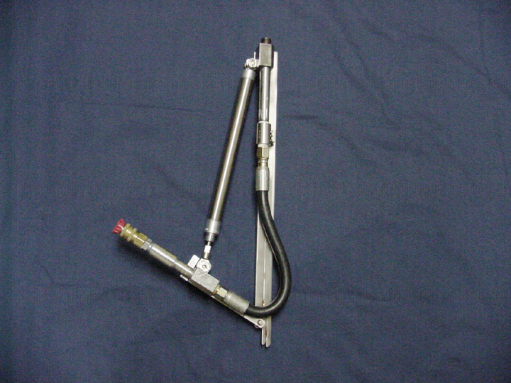
A device was needed to sample the Evaporator sidewall and supernate during an upcoming evaporator outage. A sampler was developed using a scrape head to scrape the sidewall and a sample vial to catch the sample. The scrape head assembly used a deployment mast consisting of flexible pole extensions to reach into the evaporator through a 3" diameter access pipe. The scrape sampler would travel through a sample guide pipe, through the access riser, past the tubing bundle and tie rods and against the lower cone wall behind the warming coils. The sampler would then be scraped against the wall obtaining a sample and retrieved from the evaporator, the sample vial removed and placed in a standard shipping container for shipment to the lab. A submerisble camera and optic fiber light would be mounted on the flexible mast to provide visual feedback to the operator of the sampling process and assist in insertion and removal of the sampler from the evaporator. The scrape sampling was performed several times within the Evaporator 2H pot.
2.1.2 Evaporator Pot Particulate Sampling
Upon completion of the wall scrape sample, the sampling of the loose material within the cone was desired. A Suction and Strain sampler was then developed to deploy beneath the supernate and suction and filter the material into a filter that could be shipped to the lab. A flexible pole mast was utilized by this sampler to deploy through the riser and behind the warming coils to the pot bottom. Once at the cone bottom, the suction and strain sampler had air supplied to an eductor pump causing supernate and the waste material to be suctioned into the sampler intake. The material then was exhausted along with the supernate and supply air through a filter unit. The supernate and supply air would pass through the filter leaving the solid material to remain in the filter for shipment to the lab. The Suction and Strain Sampler was deployed within Evaporator 2H with the tool taking less than one minute to suction the material desired.
2.1.3 Evaporator Pot Advanced Particulate Sampling
An advanced particulate sampler was developed to provide improved sampling of the material located in the cone within Evaporator 2H. The Suction and Strain sampler worked well for large particle sizes but tended to push smaller particles through the filter media. A sampler was needed to obtain smaller particles.
An advanced sampler was developed that provided the capability of sampling with a continuous suction without pushing the materials sampled through the filter. This vacuum sampling device, the Particulate Vacuum Sampler, pulls a vacuum on a vessel through a filter while allowing suction to remain constant. The Suction and Strain sampler pushed the sampled solids, supply air and supernate through the filter. The Particulate Vacuum sampler only pulls the solids and supernate up against the filter allowing the liquid to pass through the filter and retain the solids in a catch vial. This sampler was used successfully in Evaporator 2H.
2.1.4 Evaporator Remote Retrieval from Evaporator Entry Riser
Over time, one of the sample entry port guide pipes leading to the evaporator had become blocked by debris. Retrieval of this debris from the sample guide pipe was needed to clear the pipe to allow sampling tool access into the evaporator at that location. Two different retrieval devices were assembled for this task. The first was a very powerful earth magnet that was mounted to a retrieval cable. The magnet was lowered into the non-ferrous and non-magnetic guide pipe and used to retrieve one of the three pieces of debris.
The second retrieval device was needed to obtain the remaining two pieces of debris from the sample guide pipe. A Remote Grab Retrieval Device was used to successfully deploy down the pipe, grab the objects, and be retrieved with the debris up the sample guide pipe. The Remote Grab Retrieval Device consists of a pneumatic actuated finger, an air cylinder, a frame, and a flexible deployment mast. Control of the retrieval device is remotely operated by valve actuation. The sample guide pipe is now clear of debris and ready for use in obtaining samples from within the evaporator.
2.1.5 Remote Cutting above Evaporator
Access into a riser on the top of Evaporator 2H required the removal of a pipe jumper. Removal of the pipe jumper was blocked by an interfering lifting bail. The 1-1/8" diameter stainless steel lifting bail needed to be cut in two places and removed. A Remote Cutter was built to provide the cuts.
The Remote Cutter is equipped with a motor driven abrasive saw blade and pneumatic grippers and pneumatic cutting blade advance. The pneumatic actuation of the grippers, the advancing of the blade and the saw motor are all controlled remotely from a control panel. The cutter is flown into position by crane, the pneumatic grippers grab the part to be cut, the abrasive saw motor energized and the pneumatic advancing piston actuated pushing the spinning abrasive saw blade into the object. The Remote Cutter was deployed and successfully cut the bail in two places and removed the bail.
2.2 Evaporator 2F
Evaporator 2F was inspected due to the buildup in Evaporator 2H. Only small particulate silt-like material was present submerged in the bottom of the cone. A sample was desired of the material.
A Suction & Strain sampler was used within Evaporator 2F to obtain a sample of the fine powder submerged in the cone bottom. The sampler was deployed, air delivered to the eductor for several minutes, and the sampler retrieved and sample filter shipped for emptying in the lab. The suction intake camera mounted above the suction intake hose showed the silt-like material clouds into the water when contacted but the camera view could not help to determine if flow was traveling through the eductor and filter. The resulting sample obtained was small due to the low pressure delivered to the sampler, the coarse size of the filter used, and the very small size of particle, 3 microns.
Another Suction and Strain Sampler was built and deployed with a finer filter, increased suction, an in-field suction, an additional camera, and filter disassembly capability. The filter was finer to catch smaller particulate material. The in-field suction gauge provided a suction pressure reading in on top of the evaporator prior to sampler insertion into the evaporator to ensure the proper air flow was getting to the eductor. The additional camera was mounted above the filter to watch for flow of liquid through the filter to demonstrate that the eductor was suctioning liquid and solids up and to the filter. The filter disassembled to provide the capability for improved sample recovery in the lab. This second Suction and Strain sampler only provided a small sample amount leading to the conclusion that the material is minute within the evaporator. The development and deployments of the Suction and Strain sampler led to the development of the Particulate Vacuum sampler discussed in 2.1.3.
2.3 Evaporator 1F
1F Evaporator had not been inspected in a decade and buildup of material was found in the separator pot downstream of the evaporator. Inspection of the evaporator pot was planned and sampling equipment needed to be ready to sample whatever waste buildup was found.
Samplers for the interior of Evaporator 1F were planned. A Scrape Sampler and a Particulate Vacuum Sampler were built but an additional grab sampler was also desired. The Mini Vial Snapper was developed to deploy through the 3" access riser into the evaporator and obtain a grab sample of dried salt cake at the bottom of the evaporator cone. The Mini Vial Snapper consists of a pneumatic actuated set of jaws that are contoured to grab and retain a sample and a flexible extension mast to deploy the sampler. The jaws of the Vial Snapper can be removed from the actuator to ship the jaws with a sample to the lab. Another set of jaws can then be placed in the actuator jaws for additional sampling without cross-contaminating the samples and without need to build and use multiple actuators when obtaining multiple samples.
Inspection of the 1F Evaporator was conducted and the evaporator interior was clean with only a small amount of very fine silt-like material in the lower cone. The decision was made that not enough material was present in Evaporator 1F to justify sampling.
2.4 Evaporator 3H
2.4.1 Evaporator Exterior Sampling
Evaporator 3H cell was inspected and material was detected on the outside of the evaporator pot. This material needed to be obtained and evaluated. The material was suspected to be from a gasket leak of non-radioactive simulant used in the startup testing of the evaporator. A Scrape Sampler on an extension pole was used to sample the material and verify its non-radioactive origin.
2.4.2 Cell Cover Cleaning
The cell covers above Evaporator 3H and the top of the evaporator needed cleaning. A water lance was used to clean the cell floor but could only clean the surfaces directly below the access risers through the cell covers. Material from the top of the evaporator and on the cell walls also needed to be cleaned. A spray system developed for the 2H Evaporator pot was adapted for use within Evaporator 3H cell. The 2H spray cleaner could remotely aim a stream of 3000 psi water to clean the warming coils and walls of Evaporator 2H. The 2H sprayer could actuate 90 degrees to perpendicular to the deployment mast. The 2H spray system elbow used pneumatic actuation and could loosely be controlled by an air valve.
The 2H spray system was improved for use in Evaporator 3H cell by increasing the elbow actuating, adding an improved elbow valve, and adding a mast sleeve. The elbow range of motion needed to be increased to allow directing the spray stream at the cell ceiling. Adding an improved valve control provided more accurate aiming of the spray stream within the cell. Adding a mast sleeve helped to counteract the moments put on the mast from the spray jet on the lengthened mast needed for deployment into Evaporator 3H cell.
The 3H Directed Spray System was deployed into the Evaporator 3H cell using two different access ports. The system was used to clean the top of the evaporator and wash down the cell cover ceiling within the cell.
3. Summary
Sampling equipment, retrieval devices, a remote cutter, and a remote spray washing system were built for work supporting operation of the evaporators at the Savannah River Site. These tools successfully performed tasks that helped to keep the evaporators functioning.
4. Acknowledgements
This work was supported by the United States Department of Energy under Contract DE-AC09-96SR18500. Special thanks are extended to Christopher Allgood, William Cheng, Alvin Siddall, Kevin Counts and Malcolm Kyle for their support.
Fig. 1: Wall Scrape Sampler
Fig. 2: Suction and Strain Sampler
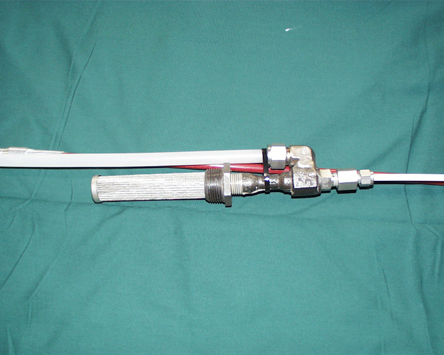
Fig. 3: Particulate Vacuum Sampler
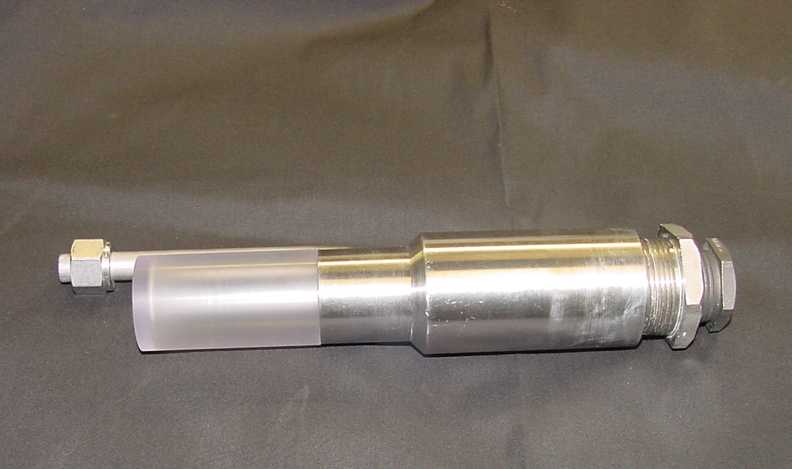

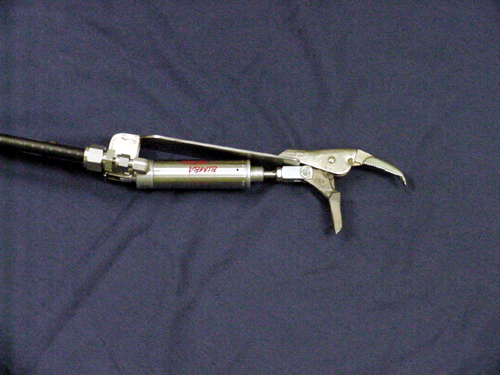
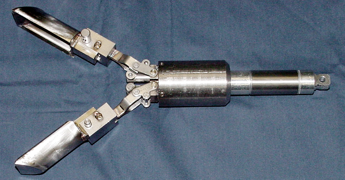
Fig. 8: Evaporator 3H Directed Spray System