WSRC-MS-2001-00605
K. J. Imrich
Westinghouse Savannah River Company
Aiken, SC 29808
This report was prepared as an account of work sponsored by an agency of the United States Government. Neither the United States Government nor any agency thereof, nor any of their employees, makes any warranty, express or implied, or assumes any legal liability or responsibility for the accuracy, completeness, or usefulness of any information, apparatus, product or process disclosed, or represents that its use would not infringe privately owned rights. Reference herein to any specific commercial product, process or service by trade name, trademark, manufacturer, or otherwise does not necessarily constitute or imply its endorsement, recommendation, or favoring by the United States Government or any agency thereof. The views and opinions of authors expressed herein do not necessarily state or reflect those of the United States Government or any agency thereof.
This report has been reproduced directly from the best available copy.
Available for sale to the public, in paper, from: U.S. Department of Commerce, National Technical Information Service, 5285 Port Royal Road, Springfield, VA 22161, phone: (800) 553-6847, fax: (703) 605-6900, email: orders@ntis.fedworld.gov online ordering: http://www.ntis.gov/support/ordering.htm
Available electronically at http://www.osti.gov/bridge/
Available for a processing fee to U.S. Department of Energy and its contractors, in paper, from: U.S. Department of Energy, Office of Scientific and Technical Information, P.O. Box 62, Oak Ridge, TN 37831-0062, phone: (865 ) 576-8401, fax: (865) 576-5728, email: reports@adonis.osti.gov
Failure of the pilot-scale test melter resulted from severe overheating of the Inconel 690 (690) jacketed molybdenum electrode. Extreme temperatures were required to melt the glass during this campaign because the feed material contained a very high waste loading. Metallurgical evaluation revealed the presence of an alloy containing nickel and molybdenum in several ingots found on the bottom of the melter and on a drip which had solidified on the electrode sheath. This indicates that a major portion of the electrode assembly was exposed to a temperature of at least 1317°C, the nickel/molybdenum eutectic temperature. Small regions on the end of the 690 sheath showed evidence of melting indicating that this localized region exceeded 1345°C, the melting point of 690. In addition to nickel, antimony was found on the grain boundaries of the molybdenum electrode. This also contributed to the failure of the electrode. The source of the antimony was not identified but is believed to have originated from the feed material.
Metallurgical evaluation also revealed that nickel had attacked the grain boundaries of the molybdenum/tungsten drain valve. This component did not fail in service. However, intergranular attack led to degradation of the mechanical properties that resulted in the fracture of the drain valve tip during disassembly. Antimony was not observed on this component.
A small pilot-scale R&D melter was being run for the U.S. Department of Energy’s (DOE) Industrial Center for Vitrification Research at the Clemson Environmental Technology Laboratory. This melter is one of several commercially available melter systems that were being tested for compatibility with various radioactive waste streams [1]. During the testing program the melter was used to evaluate vitrification of various feed chemistries from across the DOE Complex, processing parameters, and melter design/materials of construction, i.e., refractory materials and drain valves. The walls of the approximately 45 cm by 45 cm by 45 cm melter chamber were refractory lined with alumina-zirconia-silicate and high chrome K3 brick. Four Inconel 690 sheathed molybdenum electrodes, one on each wall, were installed below the molten glass level to provide Joule heating. Temperatures in excess of 1300°C were not uncommon for this melter.
At the time of failure, the melter was being fed a low-level radioactive feed containing uranium with a waste loading of approximately 70%. This new feed had a higher melting temperature than previous materials thus higher temperatures were required to produce a durable glass product. The melter temperature was controlled by power input and melt pool temperatures were periodically measured using a Type B, 304L stainless steel sheathed dip thermocouple. A melt pool temperature in excess of 1500°C was measured prior to the thermocouple failure.
Upon disassembly of the melter, severe degradation of the refractory and electrodes was observed. Further examination revealed that the 690 sheath surrounding the molybdenum electrodes had melted back to within 4 inches of the melter wall (Figure 1).
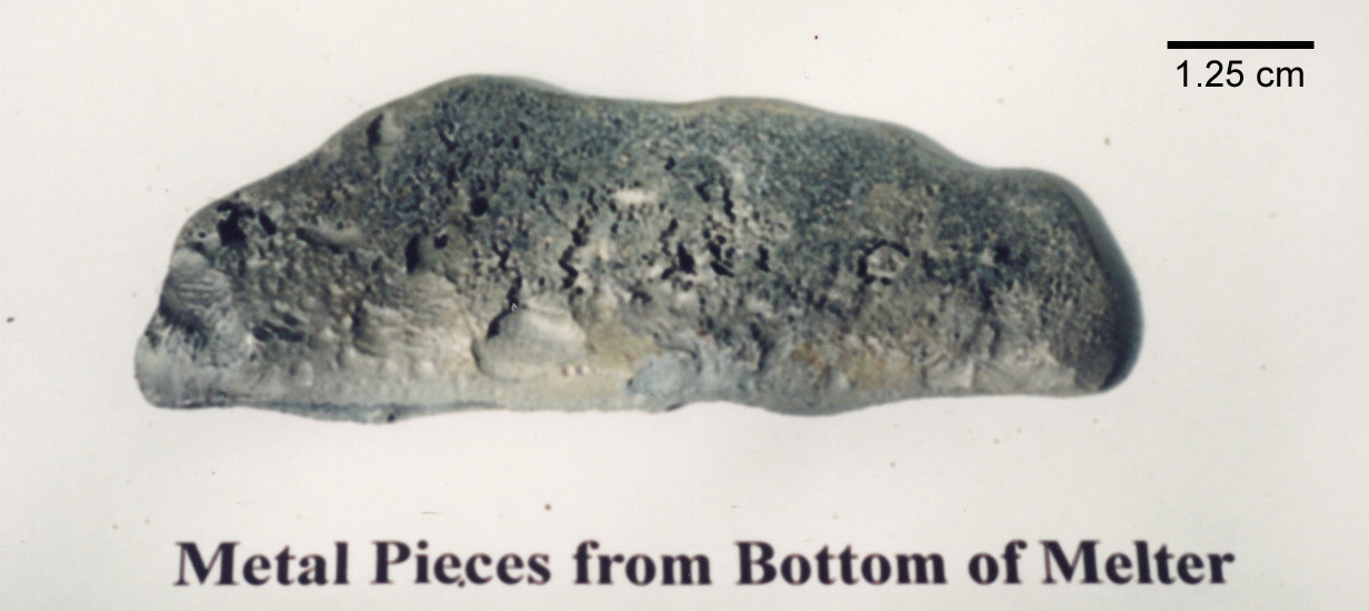
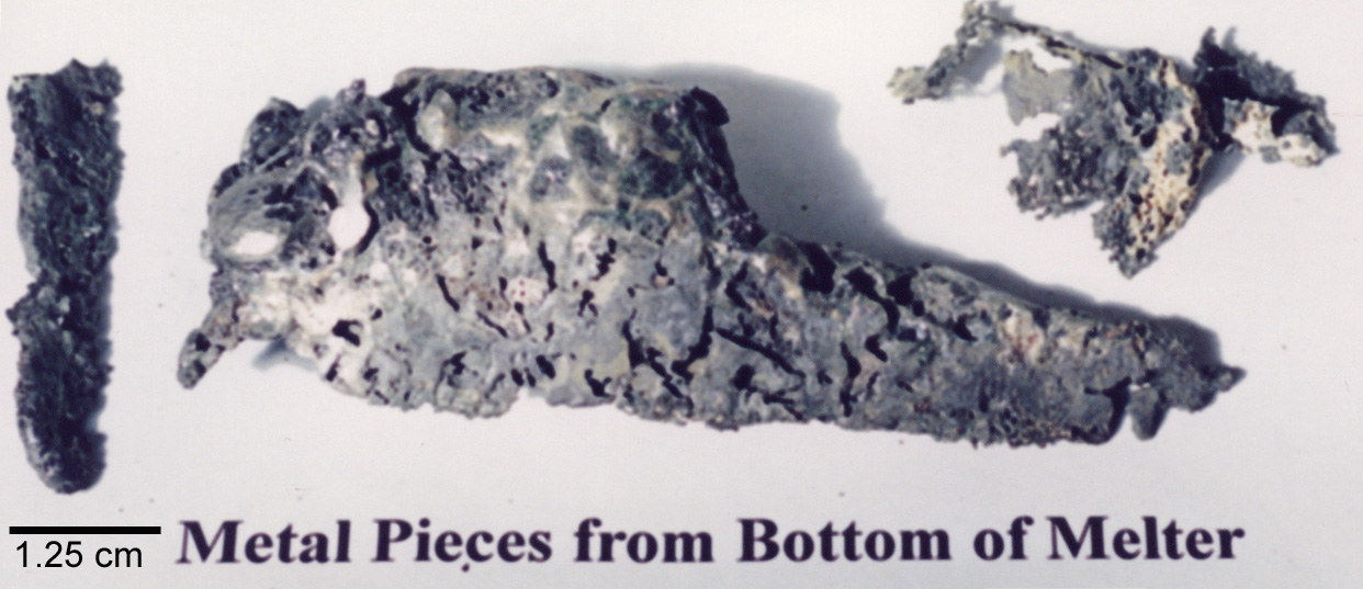
Components removed from the melter and submitted for metallurgical evaluation were a 690 jacketed molybdenum electrode assembly (Figure 2), a molybdenum/tungsten drain valve also containing a portion of the 690 holder (Figure 3), and several metal ingots (Figure 4). The ingots were found at the bottom of the melter. This report details the metallurgical evaluation of these components.
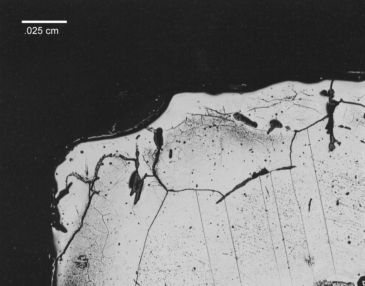
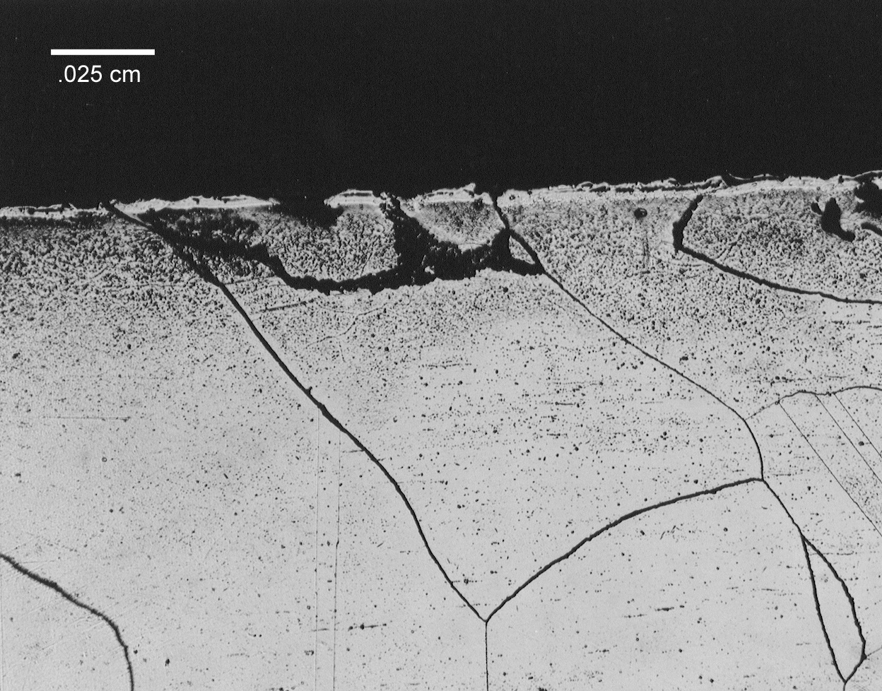
Visual examination of the electrode assembly revealed that the molybdenum electrode suffered severe pitting attack and a significant loss of cross-section. The end of the 690 sheath also showed evidence of severe degradation and only 10.2 cm (less than ½ its original length) of the sheath remained around the molybdenum electrode. The majority of the outer portion of the sheath was in good condition showing no evidence of pitting or general attack. Scale and glass deposits were adhering to the outer diameter of the sheath. A large metallic drip remained on the damaged end of the sheath and X-ray Fluorescence (XRF) analysis indicated that the drip was mainly nickel and molybdenum. Small amounts of iron and chromium were also identified in this specimen. A metallurgical specimen containing a cross-section of the sheath and the electrode was removed from the electrode assembly approximately 2.5 cm behind the damaged end of the sheath. This specimen showed no visible evidence of degradation. A non-uniform layer of glass, ranging from 0 to 0.10 cm thick was observed between the electrode and the sheath (Figure 5). No significant degradation of either the electrode or sheath was observed in this region. Alloying between the nickel and the molybdenum was also not observed at this interface. A metallographic specimen was sectioned from the degraded end of the sheath and revealed that melting of the 690 occurred at the surface (Figure 6). The melted, unalloyed region was extremely shallow, less than 0.025 cm deep. Liquation of the grain boundaries in the near surface region was not observed. Extremely large grains were evident throughout this region. Grain diameters in excess of 0.13 cm were not uncommon (Figure 6).
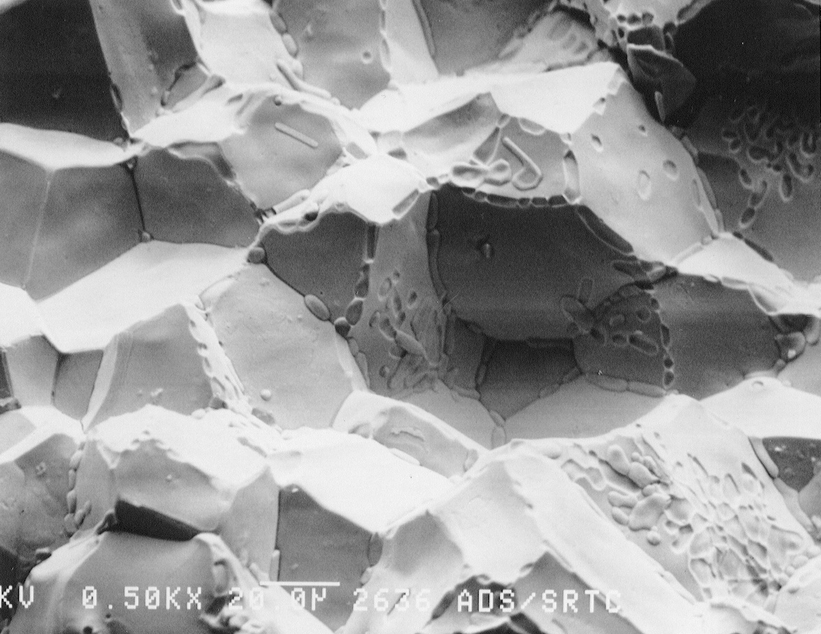
A metallurgical sample was sectioned from the severely pitted portion of the electrode. This portion of the electrode was exposed to the molten glass at the time of failure. Deposits were scraped from the outer surface and analyzed using x-ray diffraction (XRD). Results indicated that the deposits consisted of calcium aluminum silicate, lithium aluminum silicate, and trevorite. Evaluation of the molybdenum electrode using energy dispersive x-ray (EDX) spectroscopy revealed that nickel and antimony were present on the outer surface (Figure 7) and on the grain boundaries (Figure 8). The amount of antimony on the grain boundaries was significantly less than the amount of nickel. Aluminum, silicon, and trace amounts of chromium and oxygen were identified on the surface of the electrode. Several of the feed materials contained small amounts of sodium sulfate, which under certain conditions can result in severe attack of nickel base alloys. However, no evidence of sulfur was found on any of the electrode assembly components.
The two large ingots removed from the bottom of the melter had vastly different appearances. One had been completely melted and solidified into a large homogenous ingot. The other ingot was a conglomeration of smaller irregularly shaped nodules or drips (Figure 4). XRF analyses indicated that both ingots were comprised of a nickel/molybdenum alloy similar to the drip, which remained on the sheath.
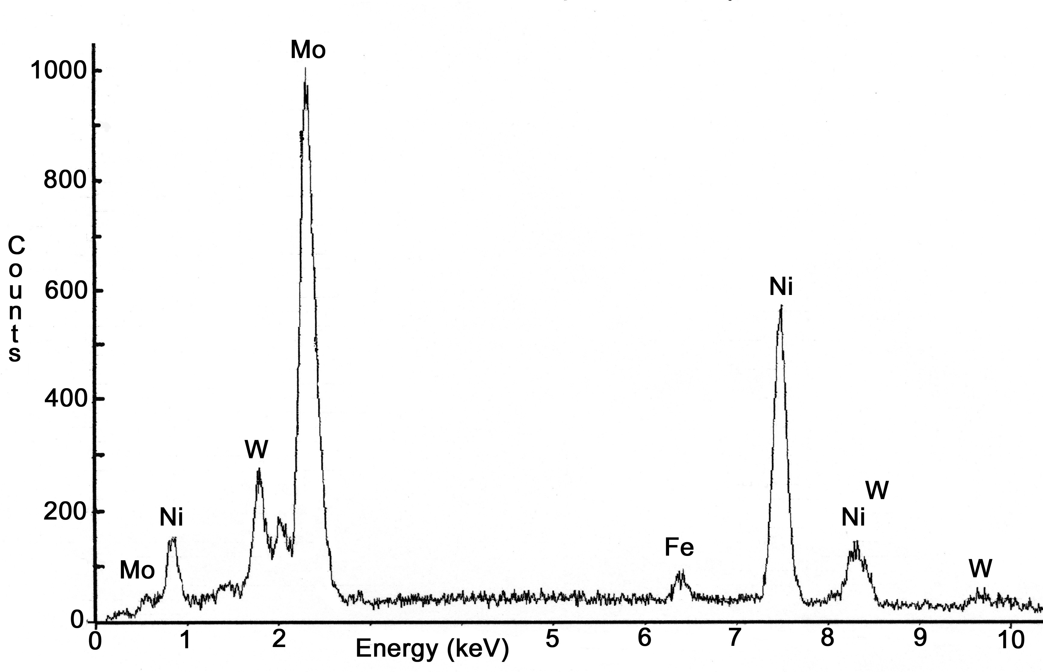
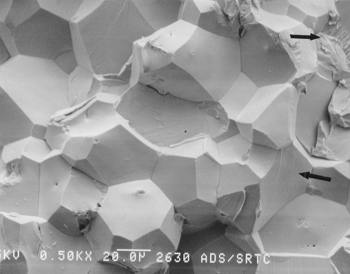
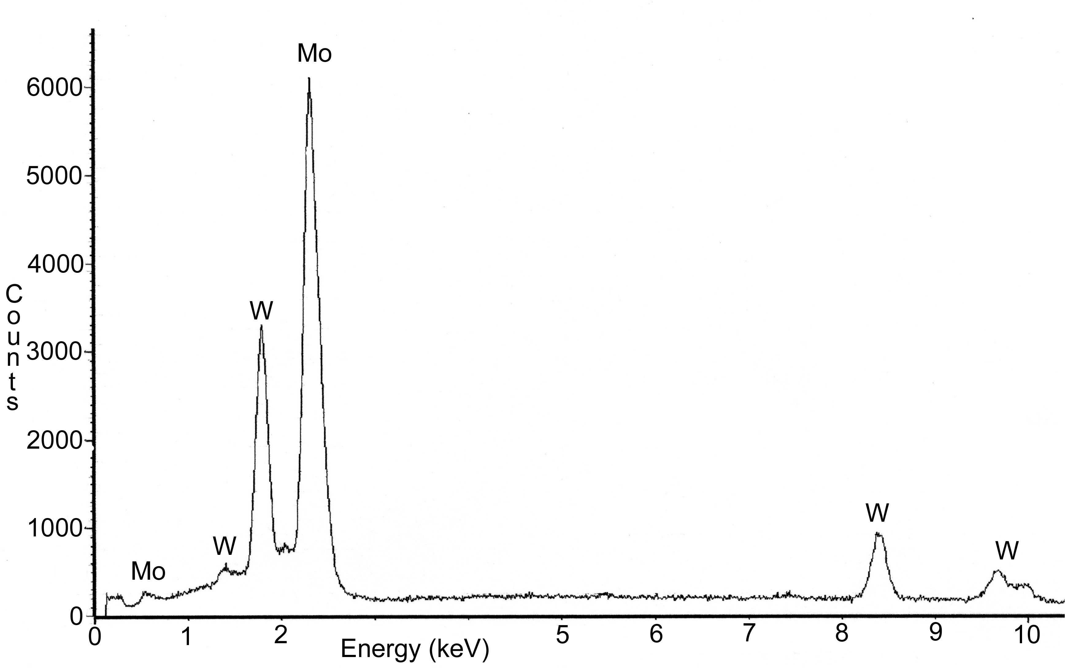
The outer diameter of the drain valve was visually examined and showed some evidence of a uniform general attack. A freshly exposed circular fracture surface was visible on the tip of the drain valve (Figure 3). This fracture surface appeared shiny and granular and did not contain any glass deposits. Further examination of this fracture surface using a Scanning Electron Microscope (SEM) revealed an intergranular fracture morphology around the outer edge. Grain boundaries around the outer edge contained discrete nodules of nickel/molybdenum (Figure 9a). Further into the center of the fracture surface, near the tip of the drain valve, a region with quasi-cleavage, intergranular and cleavage fracture morphologies, was evident (Figure 9b). Nickel was not observed on the grain boundaries in this area. Analysis of the drain valve tip by XRF indicated it was fabricated from a 30 wt% tungsten, 70 wt% molybdenum alloy. The 690 holder showed some evidence of degradation but was in reasonably good condition considering the service. Further analysis of the holder was not performed.
Nickel and molybdenum will alloy and melt at temperatures above the eutectic temperature of 1317°C [2]. Both the ingots, which were found at the bottom of the melter, and the drip sectioned form the 690 electrode sheath, were comprised of a nickel/molybdenum alloy. The majority of the material found at the bottom of the melter most likely originated from the electrode sheaths, however; a small portion may have been from the 304 L sheath on the dip thermocouple. The formation of this alloy indicates that the electrode sheath attained temperatures in excess of 1317°C. This was above the reported normal operating temperature of the melter, 1250°C. Alloying was not observed in the region between the electrode and the sheath thus, the temperature at this interface was probably much lower than 1317°C. In this location water cooling was sufficient to keep the temperature below the eutectic temperature, the operating time at temperature was short and/or the glass layer may have acted as a diffusion barrier between the nickel and molybdenum thus preventing alloying. Chromium, originating from the 690 electrode sheath and thermocouple sheath, was identified in both the ingots and the drip. Chromium concentrations in the two ingots and the drip were low. This result is expected because (1) chromium will volatilize and exit the melter through the off gas system at temperatures in excess of 1100°C and (2) chromium will go into solution with the glass. Analyses confirmed an increased chromium oxide concentration in the glass.
The metallographic specimen prepared from the end of the sheath indicated only a thin layer, less than 0.013 cm thick had melted. The melting point of 690 and the glass are 1345°C and 1150°C, respectively. Melt pool temperatures, as measured by a dip thermocouple prior to the failure, exceeded 1500°C. Complete melting of the electrode sheath probably did not occur because it was insulated by the remaining refractory and because the external water jacket was still functional and provided sufficient cooling. Grain boundaries liquation, an indication of incipient melting, was also not observed. The presence of very large grains, 0.13 cm in diameter, indicates that the sheath was exposed to extremely high temperatures. Initial grain size of the sheath was not available but the grain size for 7.6 cm diameter 690 bar stock ranges between ASTM grain size no. 4 to 5, (approximately 0.008 cm). A maximum grain diameter of 0.013 cm (ASTM grain size no. 3) was observed in 690 coupons exposed in the Integrated DWPF Melter System. These coupons were exposed to temperatures approaching 925°C over 5 months campaign (Figure 10) [3].
Nickel was observed on the grain boundaries of the electrode. The nickel was in the form of discrete precipitates indicating that the nickel diffused into the matrix and then precipitated on the grain boundaries. A greater density of precipitates was located at triple points. Diffusion of nickel and alloying of nickel with molybdenum can be avoided by maintaining the temperature below 1317°C. Some diffusion of nickel will occur below this temperature but a rapid catastrophic failure similar to the failure discussed herein should not occur. Antimony was also observed on the grain boundaries of the electrode. The antimony formed continuous network indicating it penetrated down the grain boundaries. The source of the antimony is unknown but most likely originated from the feed material. Antimony melts at 630°C. Molten antimony has been shown to dissolve molybdenum and penetrate down grain boundaries [4]. Therefore, the concentration of antimony in the feed should be minimized or eliminated to deter dissolution of the molybdenum.
An intergranular attack was observed in the near surface region of the molybdenum/tungsten drain valve. The intergranular attack resulted as molten nickel, which pooled on the bottom of the melter, alloyed with the molybdenum in the drain valve. The presence of the nickel on the grain boundaries degraded the mechanical properties of the drain valve. The clean fracture surface visible on the tip is evidence of this degradation. The center of the fracture surface failed by quasi-cleavage. This region of the valve was not in constant contact with the molten nickel and therefore weakening of the grain boundaries did not occur. Fracture of the tip most likely resulted during disassembly when the valve was removed from the solidified glass. Degradation of the drain valve by molten antimony does not appear to be a significant concern.
This is an R&D melter system that will continue to be used to test new feed materials and process parameters. New glass formulations with higher melting points are being developed to process these feed materials and to attain higher waste loadings. In addition, higher temperatures are desired to increase production rates. Thus as the maximum operating temperature of the melter is approached more frequent temperature measurements should be made to ensure that critical components are not damaged.
Failure of the pilot scale melter resulted from severe overheating of the 690 jacketed molybdenum electrode. Metallurgical evaluation revealed the presence of an alloy containing nickel and molybdenum in several ingots found on the bottom of the melter and on a drip which had solidified on the electrode sheath. This indicates that a major portion of the electrode assembly was exposed to temperature of at least 1317°C, the nickel/molybdenum eutectic temperature. Small regions on the end of the 690 sheath showed evidence of melting indicating that this region exceeded 1345°C, the melting point of 690. In addition to nickel, antimony was found on the grain boundaries of the molybdenum electrode. This also contributed to the failure of the electrode. The source of the antimony was not identified but is believed to have originated from the feed.
Metallurgical evaluation also revealed that grain boundary attack of the molybdenum/tungsten drain valve by nickel had occurred. Intergranular attack led to degradation of the mechanical properties, which contributed to the fracture of the drain valve tip during disassembly. Antimony was not observed on this component.
Figure 1. Schematic showing the melter and electrode before and
after the failure
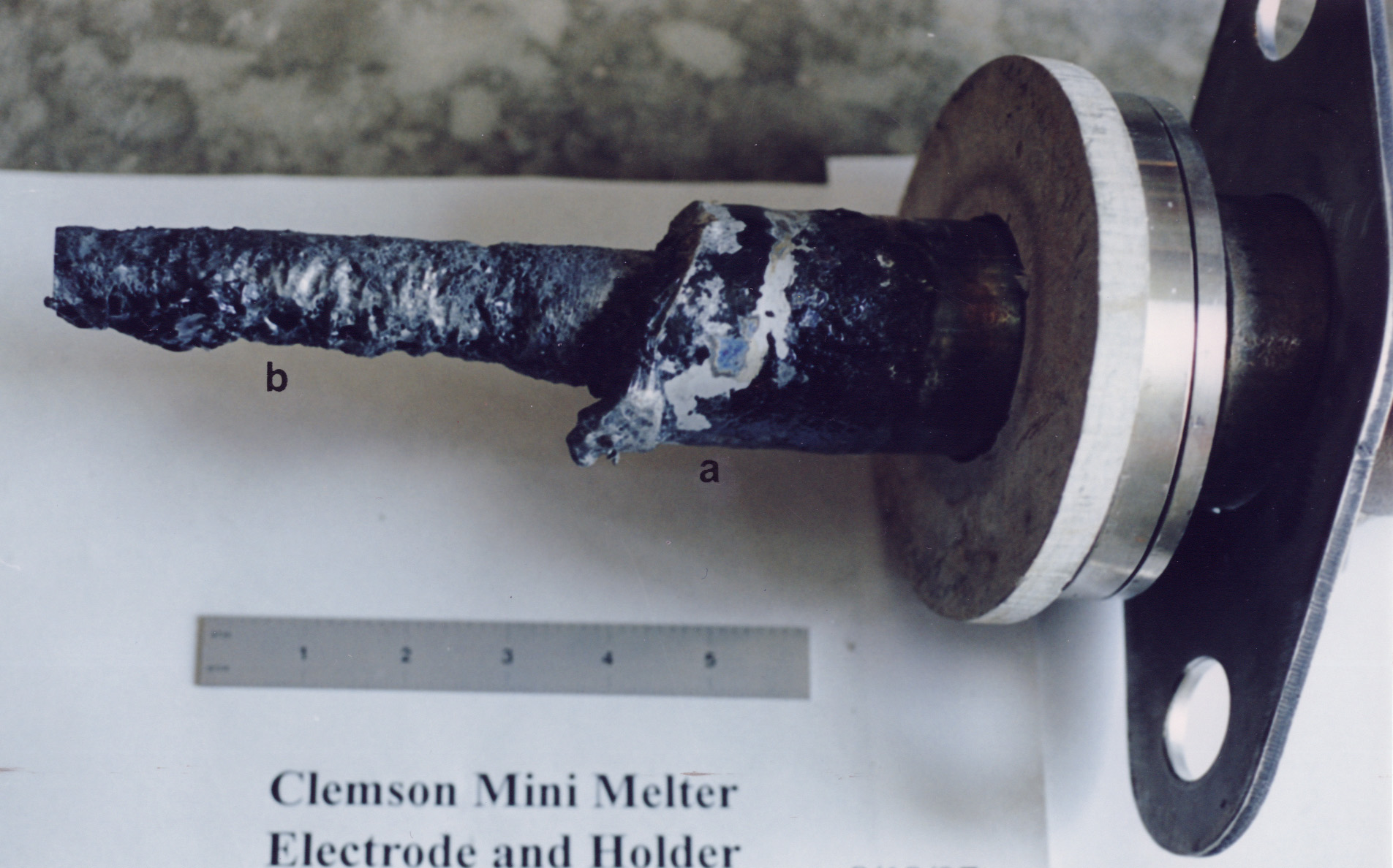
Figure 2. Melter electrode assembly. a) 690 sheath, and b) molybdenum electrode
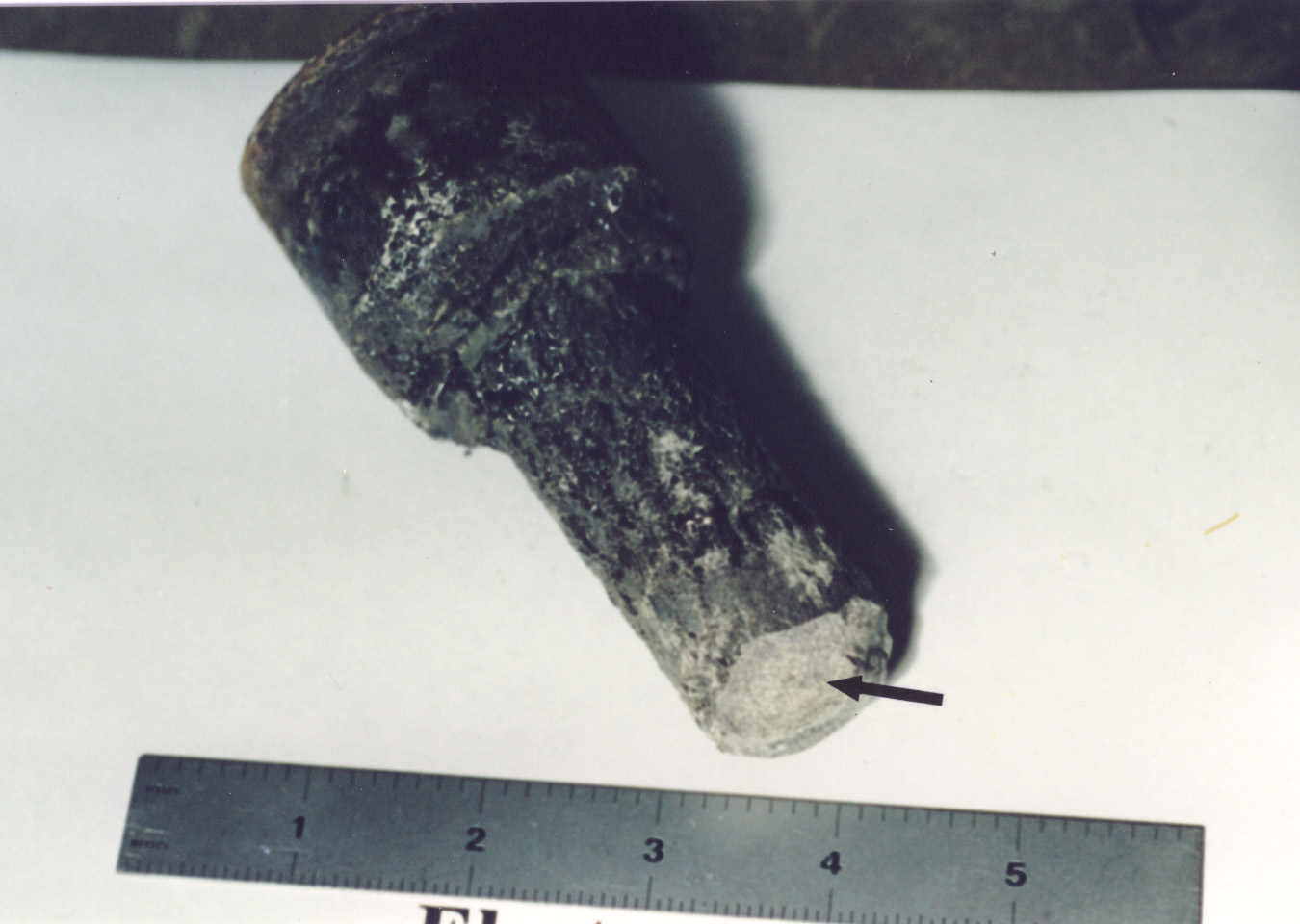
Figure 3. Molybdenum/tungsten drain valve assembly. Arrow indicates
fracture surface exposed during disassembly
(a)
(b)
Figure 4. Metal ingots removed from the bottom of the melter.
a) Homogenous ingot,
and b) ingot containing irregular shaped globs or drips
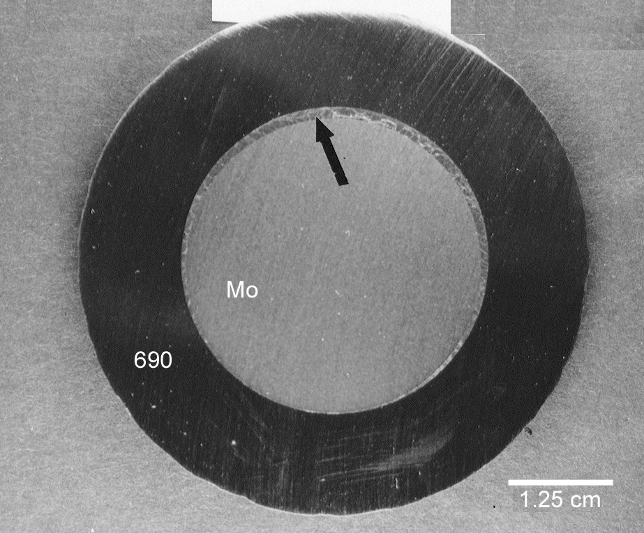
Figure 5a. Photograph showing cross section of electrode
assembly just behind melted end of sheath. A thin
glass layer is shown between the molybdenum electrode and the 690 sheath (see
arrow).
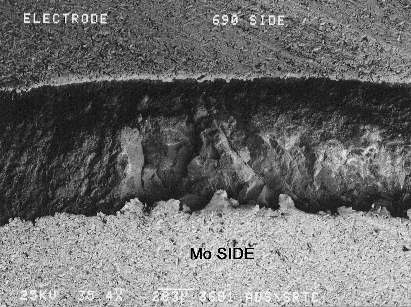
Figure 5b. SEM photograph showing glass layer. Alloying between
the molybdenum
and nickel was not present in this region.
(a)
(b)
Figure 6. Photomicrographs of specimen sectioned from melted end on 690 electrode
sheath.
a) Light area around outer edge shows melted 690. Molybdenum was not
found in this region. b) Extremely large grains in excess of 0.13 cm
were common in this region.
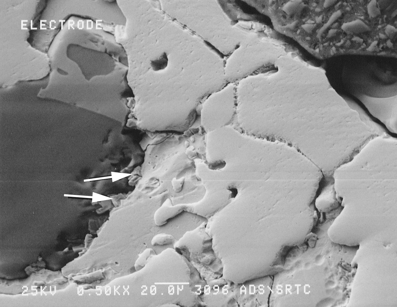
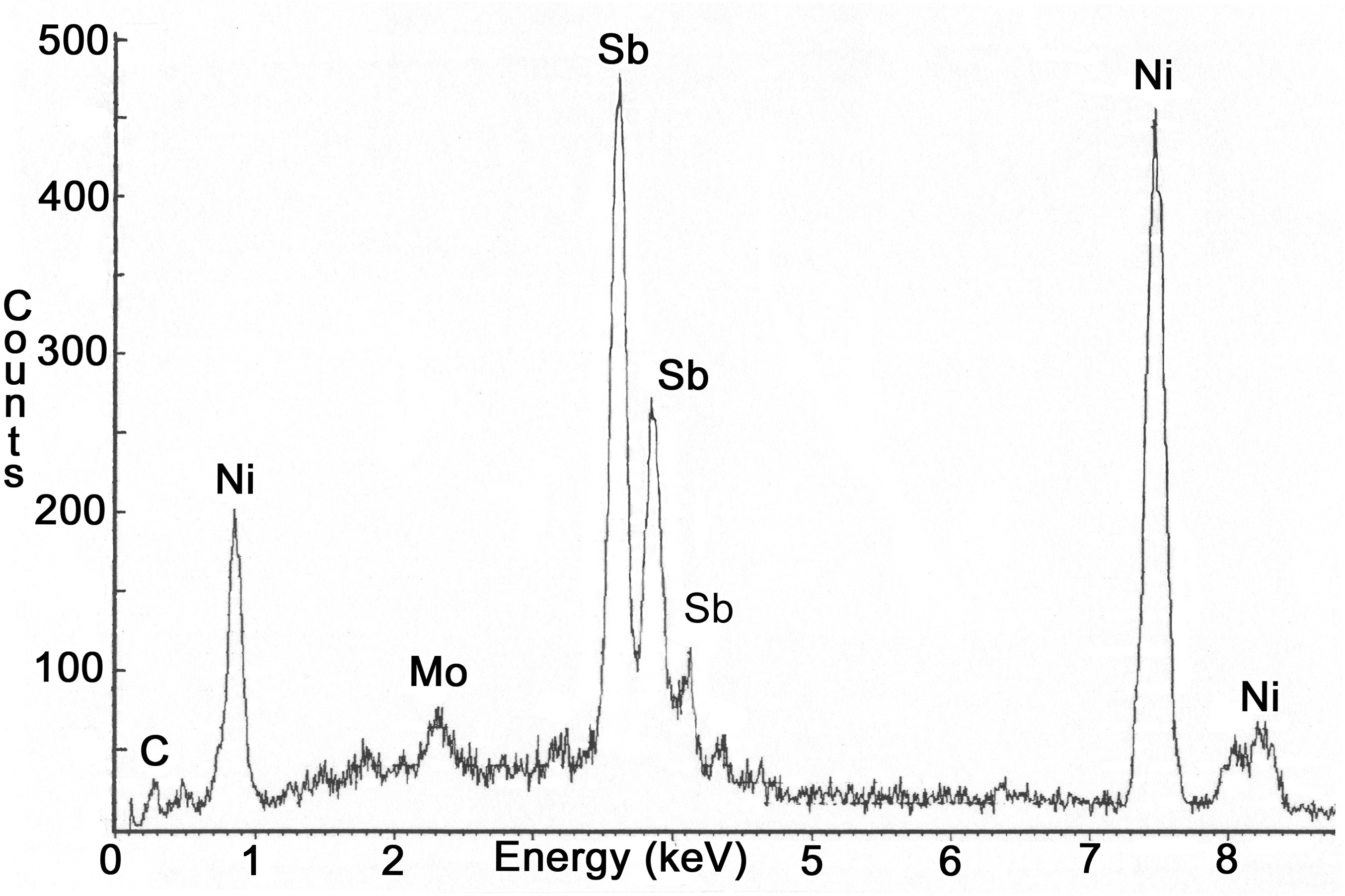
Figure 7. SEM photograph of the molybdenum electrode. EDX spectra
indicated the presence
of antimony on the surface of the electrode (see arrows). Nickel from the
Inconel sheath was also present.
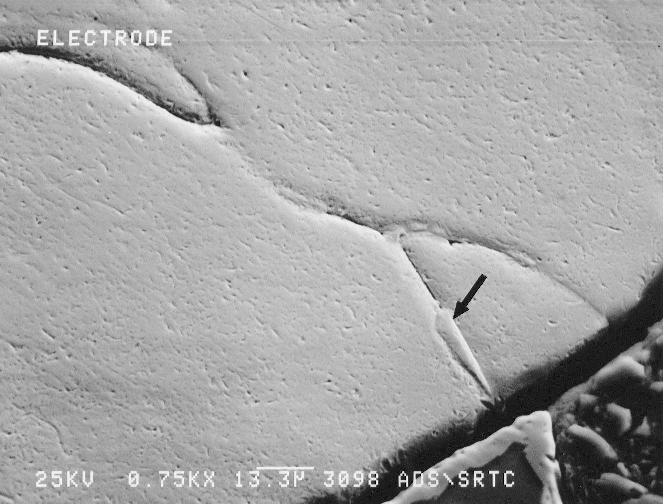
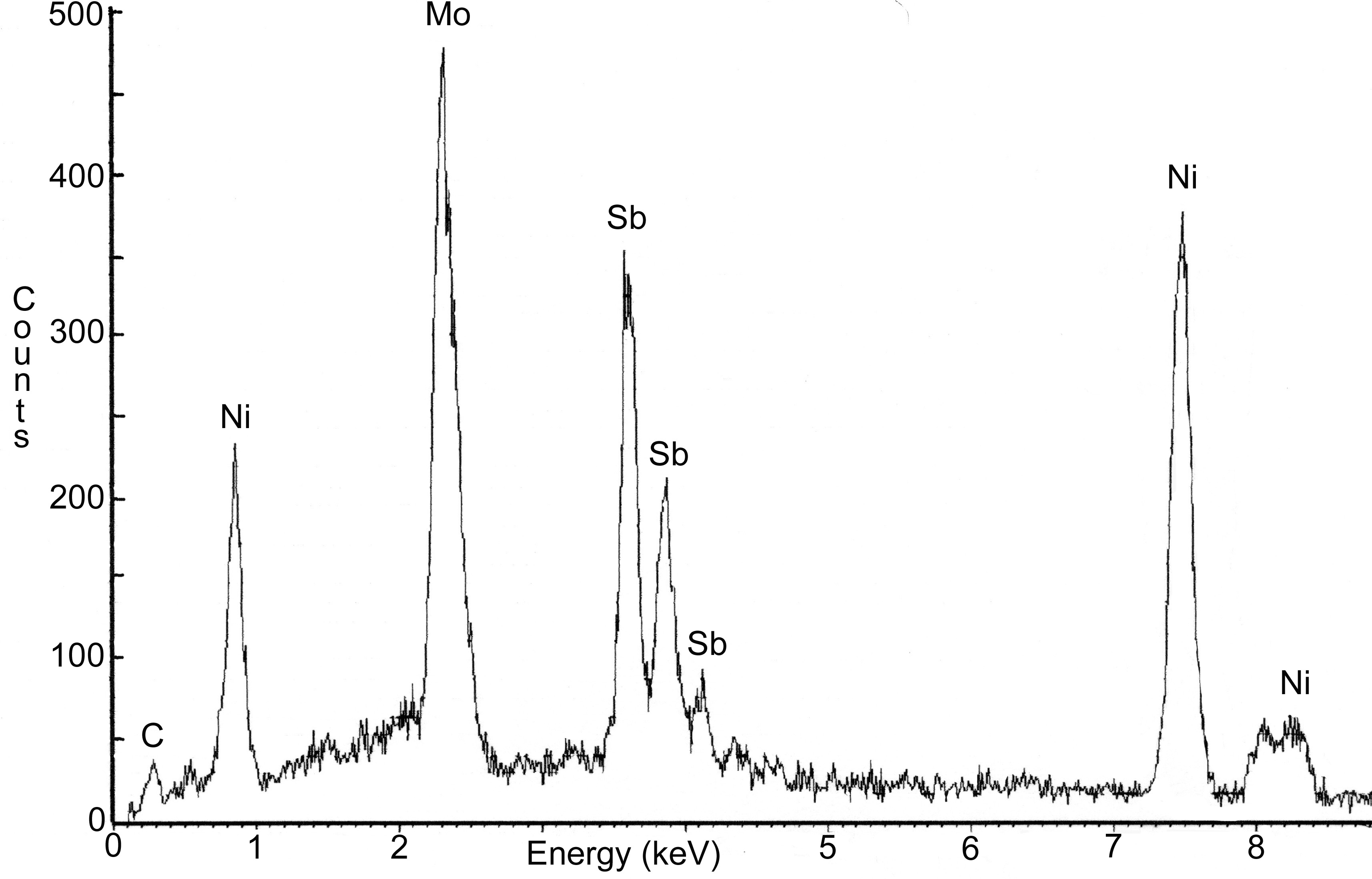
Figure 8. SEM photograph of the molybdenum electrode. EDX spectra
indicated the presence
of antimony on the grain boundaries (see arrow). Nickel from the Inconel
sheath was also present.
(a)
(b)
Figure 9. SEM photographs of the fracture surface of the drain
valve tip. a) Nickel was found on the grain
boundaries near the outer edge of the fracture surface. b) Nickel was not observed
in
the center (near drain valve tip) of the fracture surface. Arrows indicate
regions of cleavage fracture.
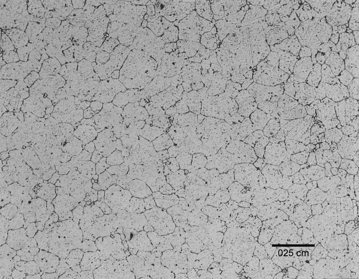
Figure 10. Photomicrograph of 690 coupon exposed at approximately 900°C for 5 months [1]