WSRC-MS-2000-00802
Remote Handling Devices for Disposition of Enriched
Uranium
Reactor Fuel Using Melt-Dilute Process
F. Heckendorn, C. Robinson, H. Haynes, and D. Fisher
Westinghouse Savannah River Company
Aiken, SC, 29808
This report was prepared as an account of work sponsored by an agency of the United States Government. Neither the United States Government nor any agency thereof, nor any of their employees, makes any warranty, express or implied, or assumes any legal liability or responsibility for the accuracy, completeness, or usefulness of any information, apparatus, product or process disclosed, or represents that its use would not infringe privately owned rights. Reference herein to any specific commercial product, process or service by trade name, trademark, manufacturer, or otherwise does not necessarily constitute or imply its endorsement, recommendation, or favoring by the United States Government or any agency thereof. The views and opinions of authors expressed herein do not necessarily state or reflect those of the United States Government or any agency thereof.
This report has been reproduced directly from the best available copy.
Available for sale to the public, in paper, from: U.S. Department of Commerce, National Technical Information Service, 5285 Port Royal Road, Springfield, VA 22161, phone: (800) 553-6847, fax: (703) 605-6900, email: orders@ntis.fedworld.gov online ordering: http://www.ntis.gov/support/ordering.htm
Available electronically at http://www.osti.gov/bridge/
Available for a processing fee to U.S. Department of Energy and its contractors, in paper, from: U.S. Department of Energy, Office of Scientific and Technical Information, P.O. Box 62, Oak Ridge, TN 37831-0062, phone: (865 ) 576-8401, fax: (865) 576-5728, email: reports@adonis.osti.gov
Abstract
Remote handling equipment is required to achieve the processing of highly radioactive, post reactor, fuel for the melt-dilute process, which will convert high enrichment uranium fuel elements into lower enrichment forms for subsequent disposal. The melt-dilute process combines highly radioactive enriched uranium fuel elements with deleted uranium and aluminum for inductive melting and inductive stirring steps that produce a stable aluminum/uranium ingot of low enrichment.
Prototypic radioactive fuel facilities are under construction at the Savannah River Site (SRS), as a design demonstration, prior to the construction of high capacity facilities at SRS. A range of post reactor fuel elements will be processed to confirm the process parameters and the remote operation facilities.
A legacy (circa 1950) remote processing cell is being converted into a cell for processing fuel elements representative of many previously used types of small reactor elements (typically one meter in length). Robotics was not available and was cost prohibitive to add in this potentially contaminated facility, so specialized remote handling devices have been designed to perform all steps involving radioactive transfers. Additionally, a teleoperated recovery device is being developed as a backup device, in the unlikely event of a wayward radioactive element/component.
Remote handling facilities are required to safely handle, and to contain the potential contamination from a variety of in-process fuel forms (e.g. fuel transfer baskets and, fuel ingots), and to handle processing components that could potentially become radiological sources, including processing crucible, and catch basins. Special design redundancies have been included to prevent mishandled or dropped components.
The remote handling systems include a series of devices that are positioned onto reference platforms over processing steps (e.g. fuel cask, melting furnace, sample removal station) by a remote crane. All remote handling operations are then conducted within the handling systems, including grasping, positioning, latching, and contamination control, with the crane serving to transfer closed devices between steps.
The aluminum/uranium fuel assemblies will be positioned in aluminum transfer baskets in existing fuel storage basins, with the basket providing the dilution aluminum as well as a transfer means. Aluminum encapsulated depleted uranium will be incorporated into the fuel basket, to prevent an extra handling step of adding it to the melt furnace. Heavily shielded casks will transfer all radioactive materials in/out of the processing facility.
Remote handling/transfer devices will be used to grapple, withdraw, and capture the fuel basket, which is approximately 1 meter long and 12 kg. After the device is relocated to the furnace enclosure, it positions the fuel basket into the graphite crucible. A different remote system is positioned on the furnace for operations during the melting process. This system provides for the taking of two molten material samples during melting and for video monitoring of the melting process.
After the end of the melting/mixing process, the sample taking device is subsequently relocated to a remote sample removal and packaging station. Then a third remote handling system is positioned on the furnace and it withdraws and weighs the final solidified ingot in its transfer container, approximately 30 kg, and transfers is to another cask.
Non-routine operations are also provided for remote handling of potentially radioactive sources, so that the cell can be reentered for maintenance or decommissioning. The furnace lining graphite crucible is the most challenging and it is remotely withdrawn into a transfer system and transferred to another shipping cask.
Extensive remote viewing systems for both remote operations and furnace interior processing monitoring are included in the facility. The devices developed are expected to serve as the basis of the large production facility to be built at SRS in several years.
Background
The Savannah River Site (SRS) is a nuclear materials production facility operated by the Westinghouse Savannah River Company (WSRC) for the United States Department Of Energy (DOE) and was established in the early 1950’s to produce nuclear materials for defense purposes. The 777 sq. km (300 sq. mi.) complex is located in South Carolina and is composed of many separate plant related operations.
The Savannah River Technology Center (SRTC) is also operated by WSRC, and its purpose is to provide technical research and support for site operations. The Remote and Specialty Equipment (RSE) group is part of SRTC, and its mission is to develop, apply, and support robotics, remote technology, and remote video/viewing to improve safety, reduce personnel radiation exposure, and reduce manpower costs.
The particular field of remote video/viewing is used extensively to extend the data gathering capabilities and control by the personnel into environments not suitable for entry. The provision for viewing remote locations from a safe distance has allowed inspection, documentation, and verification of pipes, tanks, vessels, ducts, rooms, and pits.
Introduction
Highly enriched uranium (HEU) fuel assemblies were supplied by the United States to small research reactors around the world beginning in the 1950’s, as part of the Atoms For Peace program. These assemblies are now scheduled for transfer to the Savannah River Site in the United States for long-term storage and disposition.
The highly enriched nature of the original fuel requires the post reactor fuel must be closely controlled, for non proliferation reasons. A melt and dilute methodology is being developed and demonstrated to reduce the enrichment level sufficiently to render the fuel unattractive to diversion.
The fuel elements are of a widely varying burnup and therefore widely varying radiation levels, but all will require remote handling. This paper is concerned with the remote handling methods, and equipment being developed for processing the radioactive fuels elements through the required processing steps.
It has been proposed that aluminum-based spent nuclear fuel (SNF) be processed for interim storage and ultimate geologic disposal utilizing a melt and isotopic dilution treatment process. The Savannah River Technology Center (SRTC) has been developing the Melt-Dilute process using unirradiated, surrogate assemblies containing depleted uranium and surrogate fission products in a prototype furnace and offgas confinement system.
The L-Area Experimental Facility (LEF) will provide equipment to validate the results of the SRTC technology development using irradiated SNF, provide operational melt/dilute experience, and provide additional design input for a proposed Treatment and Storage Facility project.
This program will demonstrate the concept of melting enriched uranium-aluminum irradiated fuel assemblies, alloying the enriched U-Al with depleted uranium to uniformly dilute the uranium to an enrichment of < 20% U235. It will also characterize the types and amounts of radiological isotopes released from the spent fuel during this process and demonstrate the applicable technology to capture and confine these materials.
This paper will deal primarily with the demonstration of remote material handling techniques for irradiated materials. The end products from the LEF will be solidified ingots and experimental data for design of a production facility. The test ingots produced in the LEF will be stored in monitored canisters on site and shall serve as the lead specimens in a long term monitoring program.
The HEU assemblies are composed of a variety of shapes and configurations depending on the research reactor designs. They are very similar in length with a fuel portion less than 80 cm in length and are less than 13 cm (5 in) in maximum cross sectional dimension. The similarities in size and shape are utilized in the design of a common solution. The melt dilute processed ingot is a compact cylinder approximately 17 cm (7 in) in diameter and 30 cm (12 in) high.
System Overview
The LEF is shown schematically in Figures 1 and 2 from two perspectives. The facility is being retrofitted into a legacy building in the "L" Reactor Area, to take financial advantage of existing remote cranes, shield walls, and support facilities. The existing area is protected by 1.2 meter (4 ft.) thick shield walls and a truck access moveable steel door (not shown in the Figure 1 and 2 schematic). A 1950’s era legacy building crane will be used for all remote operations and includes a 30 ton main hook and a 1 ton monorail mounted hook.
Figure 1. LEF Cell Layout North View
Figure 2. LEF Cell Layout South View
This former "truck well" portion of the reactor building is undergoing minimal modification to add a new center shield wall, to minimize any potential for personnel exposure during cask operations. A new control room facility is being added as an "office building" type of construction immediately outside of the shielded area. The location of the control building also contains the cable length sensitive power supplies to the in-cell furnace. The building cranes are not being modified but will be used "as is" due to the unpredictable nature of modification work on a legacy system.
The LEF will contain and demonstrate all portions of the remotely operated melt-dilute process by processing a limited number of all pertinent fuel element types. The operational steps include the following:
The above "routine" process is repeated as needed for each fuel element to be processed. A number of additional steps are required to remotely service the melt-dilute equipment and are addressed in following sections.
There are some expected operations that will only occur once in the facility lifetime and have been included to minimize the potential for personnel exposure at de-commissioning, which are also addressed in following sections. As further backup, a remote recovery plan has been developed to address system failures and unanticipated events.
Cell and Furnace Operations
The transfer casks are used as needed for all transfers of radiological or potentially radiological items to and from the LEF facility. The number of casks will be on an as needed basis but all will be structurally equivalent to simplify the task of remote operations. They will be transferred by truck to and from the LEF, per normal site procedures.
The cask operations will begin with personnel access to the shielded side of the new shield wall and will extend through the floor positioning of the cask, and removal of the cask lid hold down bolts. All subsequent operations, until the hold down bolts are replaced, will be done with all personnel removed from the LEF shielded areas and with the shield door secured.
The cask will be floor-positioned before the bolts are removed and during remote operations will not be raised from the floor more than a minimal distance. The casks will be positioned into one of the identical unload/load stations with the 30 ton crane.
With the exception of the above cask movement operations, all remote cell movements will utilize only the 1 ton crane, due to cell access limitations (i.e. east and west movement limitations). The cask lids are removed and replaced only while the casks are positioned in the unload/load stations.
The crane operator is located behind an existing shield window at the cask end of the LEF cell and approximately 8 meters (26 ft.) above the operating floor. Due to limitations in viewing from that position and legacy crane capabilities, the crane operator will only be required to move and position relatively large items that are indexed with "dowel" pins for positioning. All precise operations, such as fuel grasping, will utilize specialized tools controlled by the control room operator.
The furnace enclosure is removed and replaced by the crane operator to a storage location shown in Figure 1 and 2. The enclosure lid is a 1.2 x 1.6x 1.2 meter (W x L x H) (4 x 6 x 4 ft.) containment that covers the furnace during all heating operations.
All cell facilities used for unloading and loading (furnace, sample receiving station, or unloading/loading stands) use a common interface for services. A robotic tool changer is used to couple electrical and pneumatic lines between the stationary portion and the crane-moved portion, and to provide a latching of the two halves.
Remote Viewing
Remote viewing is required in a number of locations for furnace operations, routine remote operations, and all non-routine operations. A system of cameras has been developed to provide the remote views needed by both the control room personnel and the crane operating personnel. The area surveillance cameras are controllable from both locations.
A radiation hardened camera is provided to view directly into the furnace crucible during fuel melting to allow remote monitoring of the operation. The camera is shown as the center unit on the equipment plate (Figure 3). The figure shows the equipment plate assembly that is the unit that covers the top of the furnace during operation and is moved to the top of the SR during the unloading/loading operations.
The schematic shows two samplers on either side and the crucible camera assembly in the center. The camera assembly is a black-and-white unit that provides a fixed view of the melt and relies on the light given off by the melt for an image. The crucible camera assembly is removed as a unit for maintenance.
The furnace enclosure has a second camera for remote viewing of the furnace exterior from inside of the furnace enclosure during operations. It is a non radiation hardened color camera with remotely controlled pan/tilt/lens functions. The distances from the fuel are sufficient that radiation hardened components are not required for any of the other cameras for the duration of the LEF program. The enclosure camera is controllable from the control room.
Figure 3. Equipment Plate
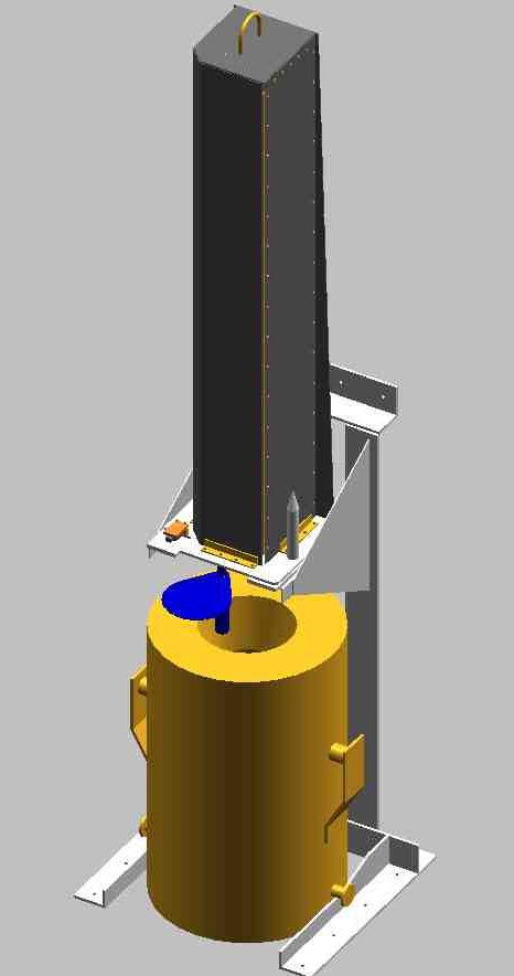
Figure 4. Cask and Typical Remote Tool
Six additional cameras are provided outside of the furnace enclosure to provide remote views of the cell. They are used to monitor furnace runs in a passive mode and to provide the remote views needed to accomplish all remote handling operations. These cameras supplement the limited visibility from the crane operator’s window.
The area surveillance cameras are controlled from either the control room or the crane operator’s overhead window location. The control room views and can record all cameras simultaneously. The crane operator can control any of the area surveillance cameras and can view the furnace and enclosure cameras, two at a time. The area surveillance cameras are positioned by the crane with four on the floor, and two straddling the new shielding wall.
All camera controls, including pan/tilt/lens, are controlled by an "over-the-coax" methodology, using commercial equipment. The coaxial cable that carries the video picture also carries the controls in the opposite direction. This technology greatly simplifies the wiring requirements and interfaces. This simplifies the moveable camera and remote tooling interfaces.
Routine Remote Handling
The equipment plate (Figure 3) provides a top to the furnace and seals in vapors. It is removed to the Sample Receiving (SR) station during furnace unloading/loading. The crane operator moves the equipment plate, after the control room operator decouples it from the datum plate, which supports it. The crane operator moves it to and from the SR and uses the 50 mm (2 in.) dowel pins to achieve proper alignment.
A SR is positioned near the end of the new shield wall and is used to remove samples taken of the melt during the melting process. Remotely deployed sample cups on two assemblies mounted on the equipment plate take samples of the still molten material at different times during the melt. These now radioactive sample cups must be remotely removed and deposited into small sample transfer "pigs". The internal functions of the SR are not a part of this report, but the equipment plate transfers are included. The movement of the sample pigs are handled remotely by the crane operator using tooling designed to adapt to the SR.
The control room operator remotely controls the samplers, both while on the furnace top and on the SR. A linear pneumatic cylinder is used to deploy the sample cups when required or to position them for cup removal. The vertical position of the cylinder is provided for the control room operator.
A cask support unload/load stand (see Figure 4) is used to interface all of the remote tools described below. All such positions have an identical datum plate with dowel pin arrangement used on the furnace and SR. Figure 4 also shows a typical remote tool already positioned on the stand. All of the remote tools below are identical on the exterior, and subsequent figures show interior views minus the contamination control exterior.
A passive mechanical device is used on all tools and the equipment plate to catch any potential contamination dust or debris that might otherwise fall out. The device is a vertically positioned door, that moves under the bottom of the tool/plate when the vertical post drops by gravity as the tool is lifted by the crane.
The handling tools (i.e. Fuel, Ingot, and Crucible) are positioned on the unload/load station or furnace top by the crane operator and then latched down by the control room operator. The internal operation of the tools is controlled by the control room operator, including internal visual monitoring and system monitoring.
All tools have a real time feedback of the vertical force on the gripper, and its vertical position. The force readout also provides weight readout of the fuel and ingot, as required. An internal video camera is provided with each tool for overview monitoring. All tools are especially designed to lock in fixed positions that do not require electrical or pneumatic services to maintain them, since the latter are not available during transfers.
The fuel handling tool (Figure 5) is used to grasp the fuel basket from the transfer cask and moves it to the furnace. A special bale alignment and locking gripper is used to engage the fuel basket bale. A second set of latches hold the fuel in the upward position during transfer.

Figure 5. Remote Fuel Handling Tool

Figure 6. Remote Ingot Handling Tool
The gripper is raised and lowered into the transfer cask below the unload/load station by a linear pneumatic cylinder that deploys the gripper to rotate, align, and grab the fuel basket. The fuel basket is a cylindrical container, which is assembled underwater in an existing basin in the area. It includes the fuel element that is combined with the aluminum needed, in the form of the basket itself, to dilute the final melted mixture and depleted uranium. The latter is encapsulated in aluminum in the upper portion of the basket. It is sent to the LEF in a transfer cask.
The fuel tool is decoupled from the unload/load station and moved to the datum plate on top of the furnace. The tool positions the fuel basket into the furnace, and is then removed to storage. The equipment plate is returned to the furnace datum plate, the furnace enclosure top is replaced, and the melting process can begin.
The ingot handling tool (Figure 6) is used after a melt to remove the fuel ingot. After a melt has cooled, the equipment plate is removed to the SR. The ingot tool is then positioned on the furnace top datum plate by the crane operator. The control room operator controls the tool to extend down into the crucible and grasp the ingot liner, which occupies the lower third of the crucible. The carbon steel liner contains the solidified fuel-aluminum-uranium mixture.
The ingot tool retracts the ingot into the tool and the crane operator repositions the tool to one of the unload/load stations. As the tool is raised, the mechanical contamination control mechanism automatically closes over the bottom opening of the tool. When the tool is in its new position, the control room operator lowers the ingot into a cask and releases the ingot. A similar reverse process is used to place a new, empty ingot liner into the furnace for the next run.
The crucible handling tool (Figure 7) is very similar to the ingot tool except that it is used to remove the entire crucible. After the ingot is removed, as described above, the crucible is removed and placed into a different cask.
The removal of the crucible is expected to be a less frequent operation that is undertaken to remove any possible radioactive sources from the furnace, to facilitate hands on maintenance. It may be necessary to periodically replace the crucible, but often the original crucible will be returned to the furnace after maintenance, etc.
The primary filter removal tool is similar to the above tools and is used to remove the primary zeolite filter bed from the equipment plate. This filter is expected to remove most or all of the radioactive species that will offgas from the melting fuel element.
A portion of the experimental work of the LEF will be to determine the efficiency of this filter; therefore, the filter will be removed for hot cell analysis elsewhere on site. The filters will be transferred to a transfer cask by the filter removal tool.
Figure 7. Remote Crucible Handling Tool
Non-Routine Remote Handling
A number of non-routine remote handling operations have been addressed that will either be infrequently required or only required at decommissioning. They have been included in the remote handling to reduce the potential for personnel exposure to as low as reasonably achievable.
A secondary filter, also consisting of a zeolite filter medium, is provided as a backup to the primary filter. It will be removed or replaced infrequently, or at least at the end of the facility life. It will be handled in a similar fashion to the primary filter.
A catch crucible is provided below the primary crucible as a backup in case of multiple system failures. This crucible will catch any molten material that might escape from a simultaneous failure of the graphite primary crucible and the carbon steel ingot liner.
As needed, the catch crucible is removed after the ingot liner and primary crucible are removed. It is removed vertically through the same center opening with a similar tool as described for the ingot and crucible tools. The details of this tool are the subject of future work.
The HEPA filter modules are intended as a backup to simultaneous failures of the primary and secondary zeolite filters and are of traditional HEPA filter media construction. The filter modules are sealed assemblies intended only for total replacement and not filter media changing. They are shown as two identical modules on the north side of the LEF cell in Figures 1 and 2.
The HEPA filter modules are designed for remote removal only, to keep system costs more reasonable. The entire frame is lifted off of the base and special air line fittings automatically disengage. The air pump and all instrumentation remains on the base. The HEPA assembly is disposed of as a unit. It is anticipated that the assemblies will only be removed at decommissioning but can be removed as needed. If replacement was required, hands on installation would be utilized.
Recovery Operations
A number of possible failure modes have been defined that exceed the routine remote handling capabilities, including several possible failures of the remote handling equipment. The methodology defined to deal with all such problems is a common, multipurpose, teleoperated mobile device.
The operations for which remote recovery is defined include all situations where radiological sources are not safely located in shielded casks. Once all sources are secured in casks, normal personnel entry techniques can be utilized.
The Big MORT device, with modifications, has been chosen for the remote recovery service. The device was previously developed at the SRTC and is a remotely controlled fork lift, which will provide the vertical reach required to address the LEF specific potential problems.
The Big MORT device will be modified by the addition of a "Schilling" robotic arm to add the additional horizontal reach and dexterity needed by the LEF. This arm is a hydraulically driven device capable of both strength and fine motor skill. It requires a hydraulic power pack, which will be installed on board of the Big MORT device.
The combined unit will be deployed by entering the cell behind the new shield wall and will be controlled from the control room. The building crane will be provide with vertical travel limits to prevent any lifting of the fuel or ingots above the top of the new shield wall to facilitate the entry of the recovery device. All other remote recovery requirements and any additional remote viewing requirements will be provided on an "as needed" basis.
Acknowledgements
Funding for the work described in this paper was provided by the U.S. Department of Energy under contract No. DE-AC09-96SR18500.
Summary
The LEF will demonstrate the process to convert radioactive post reactor HEU fuel from small experimental research reactors into a form suitable for long term disposal. The final form has been diluted with aluminum and depleted uranium to render it into a non reactive form.
The remote handling and viewing portion of the LEF will provide for all routine and non-routine operations in the radioactive processing cell, in support of the melt-dilute demonstration process. The remote operations will also provide supportive data for the design of the large scale melt-dilute system to be designed later. Innovative remote handling and viewing technologies will provide for simple but effective tooling to support LEF.