
WSRC-MS-2000-00781
Corrosion Testing in Support of the Accelerator
Production of Tritium Program
G. T. Chandler, K. A. Dunn, M. R. Louthan, Jr., and J. I. Mickalonis
Westinghouse Savannah River Company
Aiken, SC 29808
F. D. Gac, S. A. Maloy, W. F. Sommer, Jr., and G. J. Willcutt,
Jr.
Los Alamos National Laboratory
Los Alamos, NM 87545
This report was prepared as an account of work sponsored by an agency of the United States Government. Neither the United States Government nor any agency thereof, nor any of their employees, makes any warranty, express or implied, or assumes any legal liability or responsibility for the accuracy, completeness, or usefulness of any information, apparatus, product or process disclosed, or represents that its use would not infringe privately owned rights. Reference herein to any specific commercial product, process or service by trade name, trademark, manufacturer, or otherwise does not necessarily constitute or imply its endorsement, recommendation, or favoring by the United States Government or any agency thereof. The views and opinions of authors expressed herein do not necessarily state or reflect those of the United States Government or any agency thereof.
This report has been reproduced directly from the best available copy.
Available for sale to the public, in paper, from: U.S. Department of Commerce, National Technical Information Service, 5285 Port Royal Road, Springfield, VA 22161, phone: (800) 553-6847, fax: (703) 605-6900, email: orders@ntis.fedworld.gov online ordering: http://www.ntis.gov/support/ordering.htm
Available electronically at http://www.osti.gov/bridge/
Available for a processing fee to U.S. Department of Energy and its contractors, in paper, from: U.S. Department of Energy, Office of Scientific and Technical Information, P.O. Box 62, Oak Ridge, TN 37831-0062, phone: (865 ) 576-8401, fax: (865) 576-5728, email: reports@adonis.osti.gov
Abstract
The Accelerator Production of Tritium Project is part of the United States Department of Energy strategy to meet the nation’s tritium needs. The project involves the design of a proton beam accelerator, which will produce tritium through neutron/proton interaction with helium-3. Design, construction and operation of this one-of-a-kind facility will involve the utilization of a wide variety of materials exposed to unique conditions, including elevated temperature and high-energy mixed-proton and –neutron spectra. A comprehensive materials test program was established by the APT project which includes the irradiation of structural materials by exposure to high-energy protons and neutrons at the Los Alamos Neutron Science Center at the Los Alamos National Laboratory. Real-time corrosion measurements were performed on specially designed corrosion probes in water irradiated by an 800 MeV proton beam. The water test system provided a means for measuring water chemistry, dissolved hydrogen concentration, and the effects of water radiolysis and water quality on corrosion rate. The corrosion probes were constructed of candidate APT materials alloy 718, 316L stainless steel, 304L stainless steel, and 6061 Aluminum (T6 heat treatment), and alternate materials 5052 aluminum alloy, alloy 625, and C276. Real-time corrosion rates during proton irradiation increased with proton beam current. Efforts are continuing to determine the effect of proton beam characteristics and mixed-particle flux on the corrosion rate of materials located directly in the proton beam. This paper focuses on the real-time corrosion measurements of materials located in the supply stream and return stream of the water flow line to evaluate effects of long-lived radiolysis products and water chemistry on the corrosion rates of materials. In general, the corrosion rates for the out-of-beam probes were low and were affected mainly by water conductivity. The data indicate a water conductivity threshold exists to minimize corrosion in the out-of-beam areas, especially for aluminum. The in-beam probes also revealed a water conductivity threshold but at a lower value compared to the out-of-beam probes.
Keywords: on-line corrosion measurements, proton irradiation, spallation, radiolysis, water conductivity
Introduction
APT Design
The Accelerator Production of Tritium (APT) Project is part of the United States Department of Energy (US-DOE) strategy to meet the nation’s tritium needs in the 21st century.1 The APT project is coordinated by Los Alamos National Laboratory (LANL) for the Department of Energy (DOE)/Defense Programs (DP). The project involves the design of a proton beam accelerator, which will produce tritium (3H) through neutron/proton interaction with helium-3 (3He). The APT plant will consist of a linear proton accelerator and beam transport, target/blanket (T/B), tritium extraction, and heat removal systems.
Design, construction and operation of this one-of-a-kind facility will involve the utilization of a wide variety of materials exposed to unique conditions, including elevated temperature and high-energy mixed-proton and –neutron spectra. The 3He used for 3H production will be contained, at approximately 120 psi, in 6061 aluminum-T6 (6061Al-T6) pressure tubes connected to a 3H/3He-separation facility through a Type 316L stainless steel (316L) manifold. Neutrons for the 3He(n,p)3H reaction will be produced by proton induced spallation of a tungsten target clad with alloy 718. Lead blanket assemblies clad with 6061Al-T6 will moderate and multiply the spallation neutrons. The high-energy proton beam that induces spallation in the tungsten target will move from the accelerator portion of the APT system into the T/B system by passing through an alloy 718 window. The containment vessel will be fabricated from Type 304L stainless steel (304L) and 316L will be used to fabricate much of the primary cooling water system. A simple schematic of the APT system highlighting the target/blanket region is shown in Figure 1.
Corrosion-Related Design Data Needs
The T/B portion of the APT system will contain components and structures that have design lifetimes ranging from approximately 1 to over 40 years. Component replacement schedules must be established to ensure operative material degradation processes do not compromise the safety and/or functionality of the system. Because of the unique exposure conditions associated with significant portions of the APT, the amount of experimental data that directly support design lifetime determinations and replacement schedules is minimal. Corrosion-related phenomena and development of coolant and moderator corrosion control for both power and defense fission reactors has been studied extensively over the past 50 years. Less is known, however, about corrosion in cooling systems for accelerators where a variety of transient chemical species and spallation products are formed.
Therefore, a comprehensive materials test program was established by the APT project.2 This program includes the irradiation of structural materials by exposure to high-energy protons and neutrons at Target Station A6 of the Los Alamos Neutron Science Center (LANSCE) at the Los Alamos National Laboratory (LANL). This area is dedicated to long-term irradiations at maximum proton fluence (1 mA) at 800 MeV. The proton beam flux has a Gaussian distribution rotated about a central axis and nominally has a beam width at 2s = 3.5 cm. The proton flux produced in LANSCE is nearly prototypic of anticipated conditions for significant portions of the APT T/B system.
Experimental
As part of the irradiation test program, on-line corrosion probes constructed of APT candidate and alternate materials were installed in a circulating light water loop system and irradiated in the A6 target station of the LANSCE facility in 1998. The corrosion probes were located in four regions in relation to the proton beam:
Electrochemical corrosion measurements were performed with these probes to:
Corrosion Insert Design
A schematic of the LANSCE Corrosion Insert water loop is shown in Figure 2. The cooling loop has a nominal flow of 14 gallons per minute. The proton beam continuously irradiates the in-beam probes (proton flux). The near-beam probes (proton/neutron flux) are adjacent to the in-beam probes. The above-beam probes (neutron flux) are located approximately 10 inches above beam center, and the out-of-beam probes (no proton or neutron flux) are located approximately 11 feet above the proton beam and are shielded by this distance by iron. The loop has systems to inject hydrogen gas into the water and to change water pH via additions of nitric acid and lithium hydroxide. Probe designs in the out-of-beam area allow for online monitoring of water conductivity. The loop also has systems to monitor the hydrogen concentration in the water and to obtain water samples for pH, hydrogen peroxide, and conductivity measurements, and Inductively-Coupled Plasma Spectroscopy (ICP) analysis.
In-Beam Corrosion Rates
Analysis of the in-beam probes is currently being performed to determine the effects of irradiation and beam characteristics on the corrosion mechanisms of candidate and alternate materials. Figure 3 shows the calculated corrosion rates from Electrochemical Impedance Spectroscopy (EIS) data taken from an alloy 718 in-beam corrosion probe as a function of proton beam current. As shown, the corrosion rate increases with increasing proton beam current. These corrosion rates are calculated on the assumption that the entire surface area corrodes uniformly. However, the incident proton beam interaction area is small compared to the probe area. The proton beam nominally has a beam width at 2s = 3.5 cm while the probe has a diameter of 1.27 cm and 15.9 cm length. Therefore, the corrosion rate due to proton beam interaction may be much higher than calculated using the average over the entire surface. Efforts are continuing to determine the effect of proton beam characteristics and mixed-particle flux on the corrosion rate of materials located directly in the proton beam. The details of this analysis and discussion of corrosion rate characterization is presented elsewhere.3,4 This paper focuses on the analysis of electrochemical data taken from the out-of-beam probes during irradiation of the corrosion insert. The out-of-beam designation refers to samples placed in the supply stream and return stream of the flow line to evaluate effects of long-lived radiolysis products on the corrosion rates of materials.
Out-of-Beam Corrosion Probes
The corrosion probes used in the out-of-beam area consist of corrosion samples (rods; 0.125" diameter x 3" length) constructed from the APT candidate and alternate materials. Samples are threaded onto studs that are sealed in glass and joined to an NPT pipe plug style feed through. The pipe plug assembly is fitted to an in-line "bucket" on the cooling water loop at the top of the insert on the inlet and outlet sides of the water loop. The corrosion samples were constructed from candidate materials alloy 718, AISI 316L stainless steel – Nuclear Grade (316LN), 304L, 6061Al-T6, and alternate materials aluminum alloy 5052 (5052Al), alloy 625, and C276.
A flame-oxidized tungsten sample rod (W/Wox) was used as a reference electrode and three C276 samples were used together as a counter electrode for the electrochemical measurements. A modified version of the three electrode out-of-beam corrosion probes was used to measure changes in water conductivity. A conductivity probe was placed in both the supply and return sides. An in-line hydrogen sensor located well above the beam area was used to periodically measure the dissolved hydrogen concentration in the cooling water loop. Thermocouples were also used to monitor temperature in the supply and return sides of the corrosion loop.
Electrochemical Impedance Spectroscopy Measurements
Electrochemical Impedance Spectroscopy (EIS) measurements were used to determine real-time corrosion rates of materials in the corrosion insert environment. Data were collected from the probes at open circuit potential over a frequency range of 1000 Hz down to 0.002 Hz with an applied ac voltage of 30 mV. Figure 4 shows a typical Bode magnitude and phase plot for an out-of-beam supply side alloy 718 probe. The data was modeled using a simplified Randle’s electrical equivalent circuit. A non-linear least squares fit of the impedance data (Zimaginary versus Zreal Nyquist plot) or the Bode magnitude and phase plot was performed to determine values of material polarization resistance, Rpol and solution resistance, Rsol.
All other candidate and alternate materials except 6061Al-T6 and 5052Al had Bode magnitude and phase data characteristic of the alloy 718 data. Figure 5 shows typical EIS Bode phase data of an out-of-beam supply side 6061Al-T6 probe. An obvious shoulder in the magnitude data is observed. The possible explanations for a second time constant in the data include the formation of a hydrated layer on the surface of the aluminum probes or localized corrosion such as pitting and/or crevice corrosion. In studies performed by Mansfield and Kendig, a second time constant in EIS data of Al alloys exposed to high chloride concentrations was attributed to pitting.6 The effect of chloride concentration on the susceptibility of Al-clad fuels in water storage basins to pitting has also been studied at SRS.7 Cyclic polarization testing of 6061Al has indicated that breakdown of the passive film can occur with as little as 7.5 ppm chloride. Solutions containing soluble salts of copper and bicarbonate can also have an accelerating effect on the pitting susceptibility of aluminum. The water used in the LANSCE corrosion loop during the EIS measurements, however, is expected to have very low levels of chloride.
Pitting has been observed in aluminum tubing irradiated at LANSCE as part of the Al/SS transition joint testing.8 The pitting was attributed to copper deposits on the aluminum surface. The copper was present in that water system due to contact with a copper beam-stop component. Copper is not expected to be present in the corrosion insert water system. Chemical analysis of water samples taken from the corrosion insert are currently being performed.
A plausible explanation for the second time constant may be due to the added resistance of a precipitated hydrated aluminum layer on the surface of the probes. The equivalent circuit model for this impedance is shown in Figure 6 where Rpol represents the polarization resistance of the corroding surface, Rsol represents the solution resistance, and Rlayer represents the resistance of the suspected layer. A non-linear least squares fit of the data with this model was performed to determine values of Rpol.
Corrosion rates were calculated from Rpol data using the following equation:

Results and Discussion
Effect of Water Conductivity
Initial irradiation testing with the corrosion insert was performed with only the corrosion insert present in the LANSCE proton beam target station. EIS data were measured with the corrosion probes under various conditions over a 10-day time period. A 6% Hydrogen / 94% Argon gas mixture was bubbled into the water system at approximately 0.3 ppm during the first phase of testing. The average supply and return side water temperature during this phase of testing was approximately 30° C. In-beam measurements were performed at average beam currents of 10, 35, 95, and 340 m A. Out-of-beam measurements were performed when the average beam current reached 340 m A. After the first phase of testing, the corrosion loop water system was drained, flushed, and refilled. Measurements of in-beam alloy 718 probes were then performed with various beam conditions with hydrogen injected into the water system. Again, the corrosion loop water system was drained, flushed, and refilled. EIS measurements were then performed on all of the corrosion probes over a 60-hour period with a proton beam current of 340 m A in the beam area with no hydrogen injected into the water system.
Figure 7 shows the change in water conductivity and dissolved hydrogen concentration over this initial test period with indications of when the system was drained, flushed, and refilled. During the first phase of testing, the water conductivity measured in-line on the supply- and return-sides showed an increase from 0.8 microSiemens per centimeter (m S/cm) (prior to beam-on to a maximum of approximately 75 m S/cm and then a decrease to approximately 25 m S/cm at the end of testing. A similar trend was observed in previous testing performed in 1997, however, the conductivity range was slightly lower at 15-25 m S/cm over the period of testing. The hydrogen concentration measured in-line well-above the beam behaved similarly; 0.4 ppm prior to beam-on reaching a maximum of 3.1 ppm and then decreasing to 1.2 ppm at the end of testing. Although components of the corrosion loop system were thoroughly cleaned prior to testing, the initial increase in conductivity is likely due to the breakdown or removal of residues or foreign materials, such as oils or films, from the system and component surfaces. The eventual decrease in conductivity and hydrogen concentration may be due to a self-cleaning effect of the irradiation.
As shown in Figure 7, the water conductivity and hydrogen concentrations were significantly lower during the second and third phases of testing after the water system was drained, flushed, and refilled. The water conductivity and dissolved hydrogen concentration was approximately 3 m S/cm and 0.5 ppm, respectively, during the second phase of testing with hydrogen injected into the water system. During the no hydrogen injection runs, the conductivity was very low at 1.3 m S/cm and the hydrogen concentration was 0.4 ppm. Similar results were observed in testing performed in 1997.
By comparing the calculated average corrosion rates of the various out-of-beam materials under the different water conductivity regimes from the 1998 and 1997 irradiation tests, the effect of water conductivity on the corrosion rates can be seen. This data is summarized in Figures 8-9. Low average corrosion rates on the order of <0.01-0.04 mils per year (mpy) were calculated for candidate materials alloy 718, 316L, and 304L and alternate materials Hastelloy C276 and alloy 625 under the highest water conductivity range measured at 25-75 m S/cm and dissolved hydrogen concentration of 1-3 ppm. In general, the return side probes had slightly higher corrosion rates compared to the supply side, which is most likely due to a higher concentration of radiolysis products in the return side due to buildup on the return side and additions of makeup water to the supply side. Corrosion rates for 6061Al-T6 and 5052Al were significantly higher compared to the other materials at approximately 1 mpy under the same high conductivity conditions. However, the aluminum corrosion rates decreased significantly with a decrease in water conductivity. The corrosion rate of 6061Al decreased by 2 orders of magnitude to 0.01 mpy with a decrease in the water conductivity below 25 m S/cm and dissolved hydrogen concentration to 0.3 ppm. In general, the corrosion rates for the other candidate materials and alternate materials decreased by a factor of 5-10 with the decrease in water conductivity. The data indicate that a water conductivity threshold exists to minimize corrosion in the out-of-beam areas, especially for aluminum.
Cyclic polarization studies have been performed at the Savannah River Site (SRS) as part of the aluminum-based spent fuel basin management program to evaluate the region of "aggressive" water qualities where existing oxide films on aluminum alloys would tend to break down and pits would initiate and remain active. Based on the laboratory testing and experience of long-term exposure of aluminum fuels in water storage basins, low conductivity water (<50 m S/cm) should not be aggressive to cause pitting corrosion.7 6061Al alloys did show a higher susceptibility to pitting corrosion compared to 1100Al and 8001Al in water test solutions containing chloride additions only. However, a significant decrease in measured current densities in the cyclic polarization testing of 6061Al was observed when the water conductivity was below 25 m S/cm, which follows the trend that is observed in the out-of-beam LANSCE corrosion tests.
Irradiation Time Study
EIS measurements were also performed with out-of-beam corrosion probes over an extended period of time to evaluate the effect of buildup of radiolysis products and water chemistry on the corrosion rate. These measurements were performed over a 51-day period. The average beam current in the beam area was approximately 1000 m A with all of the materials test inserts in place in front of the corrosion insert in the LANSCE Target Station. The temperature of the supply and return regions was approximately 35° C during the irradiation time study compared to 30° C when the corrosion insert was tested by itself at a lower beam current of 340 m A. The water conductivity was on the order of 1-3 m S/cm. The hydrogen concentration 0.15-0.6 ppm.
All of the materials exhibited low corrosion rates and did not show significant change with time. Alloy 718, 316L, 304L, C276, and alloy 625 had corrosion rates <0.005 mpy over the time period studied. Higher corrosion rates were observed in the 6061Al and 5052Al at 0.02 – 0.09 mpy. A slight increase in corrosion rate of aluminum was observed with the gradual nominal increase in water conductivity.
Comparison to In-Beam Results
Figure 10 shows the comparison of the average corrosion rates of the out-of-beam probes versus the in-, near-, and above-beam probes for alloy 718 and 316L. The in-beam and near-beam probe corrosion rates are calculated on the assumption that the entire surface area corrodes uniformly. Correlations with flux distributions and beam characteristics are currently being performed to provide an accurate corrosion rate in-beam and near-beam relative to APT conditions.
As shown in Figure 10, the corrosion rate of the in-beam probe is significantly higher compared to the near-beam and above-beam probes. A 3X decrease in corrosion rate is observed between the in-beam probes and the above-beam probe. The above-beam probe is expected to have very little proton irradiation and a factor of 10 lower neutron irradiation compared to the in-/near-beam probes. The out-of-beam return probes showed only a slight decrease in corrosion rate compared to the above-beam probe. The data also indicates that a water conductivity threshold also exists for the in-beam probes but at a lower value of 1-2 m S/cm.
Conclusions
Based on the data presented in this paper, the following conclusions can be made:
References
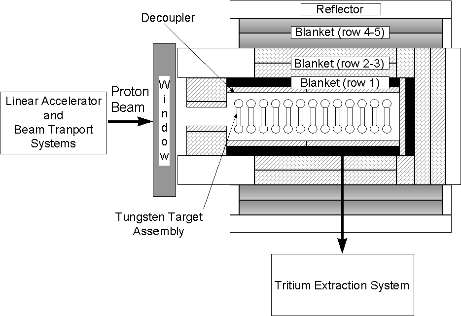
Figure 1. Schematic of the APT system highlighting the Target/Blanket (T/B) system.
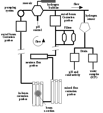
Figure 2. A diagram representing the corrosion diagnostics to
be used on the cooling water loop
at the LANSCE A6 target station. The proton beam is perpendicular to the
diagram and is represented by the oval over the top of the in-beam
corrosion probes.
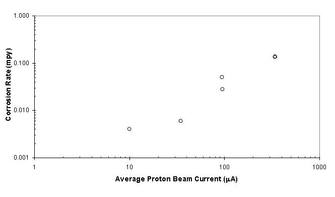
Figure 3. Average corrosion rate of Alloy 718 as a function
of proton beam current at the beam centerline.
The corrosion rate is based upon the total surface area of the probe.
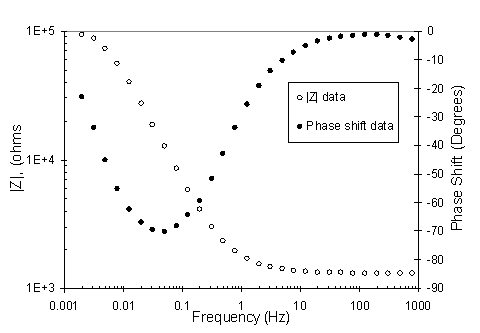
Figure 4. Bode magnitude and phase plots of EIS data taken from an out-of-beam supply side Alloy 718 probe.
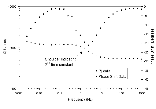
Figure 5. Bode magnitude plot of EIS data taken with an out-of-beam supply side 6061Al-T6 probe.
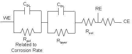
Figure 6. Modified Randle’s equivalent circuit model with a
hydrated aluminum layer used to model
EIS data taken with out-of-beam probes constructed of 6061Al and 5052Al.
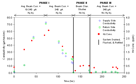
Figure 7. Water conductivity and dissolved hydrogen concentration
measurements in the LANSCE Corrosion
Insert during initial irradiation testing with only the corrosion insert present
in the Target
Station. (Maximum average proton beam current = 340 m
A. Solid lines indicate
drain, flush, and refill operations. The time between drain and beam back on
is
typically 1-3 days.)
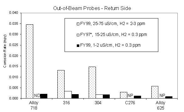
Figure 8. Average corrosion rates for out-of-beam return side
corrosion probes during LANSCE irradiation
testing with an average proton beam current of approximately 340 m
A.
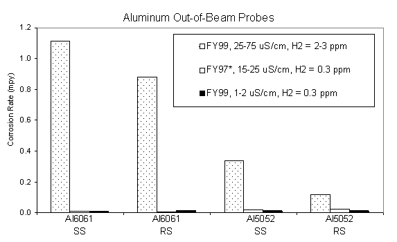
Figure 9. Average corrosion rates for out-of-beam aluminum probes
during LANSCE irradiation
testing with an average proton beam current of approximately 340 m
A.
Notes for Figures 10-11: ND = No Data, NP = No Probe
* Data adapted from LAUR 98-3601, "Materials Corrosion and Mitigation Strategies for APT, End of FY ‘97 Report: II. Out-of-Beam Corrosion Rates and Water Analysis from the ‘97 A6 Irradiation," R. S. Lillard, D. Pile, and D. Butt.
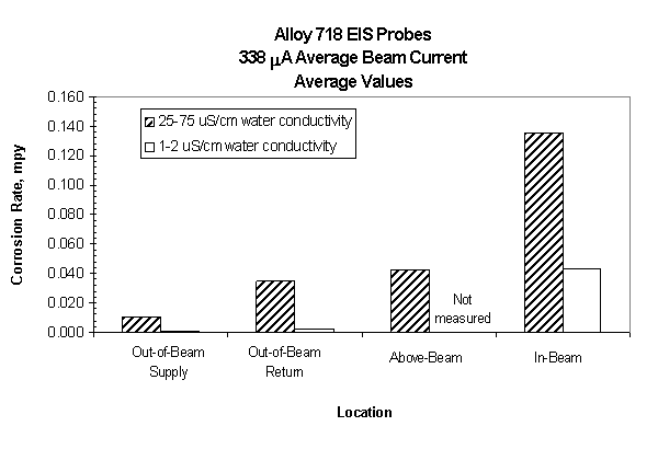
Figure 10. Average corrosion rate of Alloy
718 probes as a function of location relative to the proton beam
and water conductivity. Average beam current is 340 mA
with only the corrosion
insert present in the LANSCE target area.